


Maintenance
39
6.
Adjust the pressure regulator to the desired operating or equalization pressure. See
Specifications.
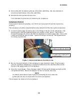
Slowly,
fully open the adapter fitting’s valve. Charge the system with helium
gas until the desired pressure is indicated on the compressor’s pressure gauge.
7.
Close the adapter fitting’s valve and the gas cylinder valve.
8.
Disconnect the charge line from the adapter fitting. Store the charge line to keep it clean.
9.
Reinstall the dust plug on the adapter fitting. With two wrenches, remove the adapter fitting.
10.
Reconnect the return gas line or the gas manifold to the compressor. Torque the coupling
to 4.85 ± 0.7 kgf m (35 ± 5 ft. lbs.).
This completes the charging procedure using a charge/vent adapter fitting.
Venting Procedure to Adjust the Equalization Pressure
Tools required: Adapter fitting P/N 266395C or 255919B2
Open end wrenches 1", 1 1/8", 1 3/16"
1.
Stop the compressor.
2.
Using two wrenches, disconnect the supply gas line or the supply gas manifold assembly
from the compressor.
3.
Be sure the valve on the adapter fitting is closed. Using two wrenches, attach it to the
supply coupling on the compressor.
4. Slowly
open the valve on the adapter fitting. Vent the compressor until the required
equalization pressure is attained. See Specifications. Close the valve on the adapter fitting.
5.
Remove the adapter fitting.
6.
Reconnect the supply gas line or the gas manifold to the compressor. Torque the coupling
to 4.85 ± 0.7 kgf m (35 ± 5 ft. lbs.).
This completes the procedure for venting to adjust the equalization pressure.
Venting Procedure to Vent to Atmospheric Pressure
Tools required: Adapter fitting P/N P/N 266395C or 255919B2
Open end wrenches 1", 1 1/8", 1 3/16"
#2 Phillips screwdriver
This procedure includes disconnecting the adsorber to prevent venting it.
1.
Stop the compressor and disconnect the power from the compressor.
2.
Using two wrenches, disconnect the supply and return gas lines or the gas manifolds from
the couplings on the compressor. Screw dust plugs into the disconnected gas lines.
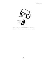
3.
Remove the compressor’s side panel nearest the gas supply coupling.
Summary of Contents for HC-4E1
Page 2: ......
Page 8: ...4 This page is intentionally blank...
Page 10: ...6 This page is intentionally blank...
Page 12: ...8 This page is intentionally blank...
Page 20: ...16 This page is intentionally blank...
Page 26: ...22 This page is intentionally blank...
Page 38: ...34 This page is intentionally blank...
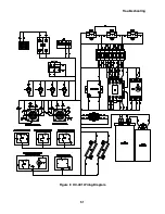
Page 55: ...Troubleshooting 51 Figure 9 HC 4E1 Wiring Diagram...
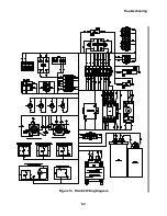
Page 56: ...Troubleshooting 52 Figure 10 HC 4E2 Wiring Diagram...
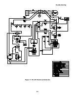
Page 57: ...Troubleshooting 53 Figure 11 HC 4E1 Electrical Schematic...
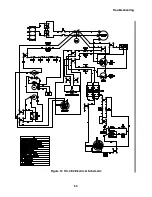
Page 58: ...Troubleshooting 54 Figure 12 HC 4E2 Electrical Schematic...
Page 61: ...Parts 57 Figure 13 Parts Identification 18 21 19 13 14 20 16...


