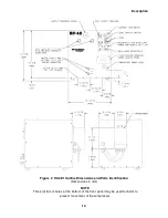


Installation
28
Field Wire the Compressor
Tools required: #2 Phillips screwdriver
Flat blade screwdriver
(2) Open end wrenches, 33mm (1 5/16”)
The HC-4E1 Compressor is normally furnished with a power cord attached. However, the
compressor can be hard wired to customer’s power source if required.
To hard wire the compressor, first remove the power cord from the compressor.
1.
Disconnect the power cord from the customer’s power source.
2.
Using two 33 mm wrenches, loosen, but do not remove, the power cord strain relief on the
front panel. Use one wrench to hold the strain relief body and one to turn the jam nut.
3.
Remove the field wiring access cover on the front panel to gain access to the terminal block.
4.
With a flat-blade screwdriver, loosen the power cord terminal screws and the ground
connection. Remove the two hot leads and ground.
5.
Remove the complete power cord.
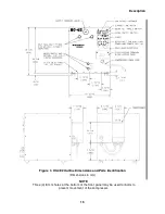
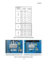
Instructions for field wiring follow. Use 12 AWG (3.3 mm
2
) copper wire with oil-resistant
insulation. Two power leads and one grounding conductor are required. Be sure that the
customer’s electrical service conforms to the specifications.
When using 3/4” rigid conduit:
1.
Remove the strain relief fitting from the compressor’s front panel. Attach ¾” conduit to the
front panel using a connector sized for a 28-mm (1 3/32") hole. This is the National
Electrical Code’s standard size for ¾” (26.7 mm) conduit.
2.
Attach ¾” conduit to the front panel using a connector sized for a 28-mm (1 3/32") hole.
This is the National Electrical Code’s standard size for ¾” (26.7 mm) conduit.
3.
Feed the conductors through the conduit. Insulated conductors should extend
approximately 125 mm (5") from the end of the conduit into the compressor enclosure. Strip
9 mm (0.35”) of cover from the end of each conductor. Twist the stranded conductors to
prevent fraying when feeding the wires into the terminal block.
4.
Connect the two power leads to the terminal block. Connect the ground wire to the
grounding screw next to the terminal block.
5.
Reinstall the terminal block access cover.
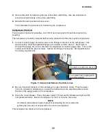
When using flexible cable:
1.
Strip off 100 to 150 mm (4" to 6") of the cable’s outside cover to expose the individual
insulated conductors. Strip 9mm (0.35”) from the end of each conductor. Twist the stranded
conductors to prevent fraying when feeding the wires into the terminal block. Feed the cable
through the strain relief fitting.
2.
Connect the two power leads to the terminal block. Connect the ground wire to the
grounding screw next to the terminal block.
Summary of Contents for HC-4E1
Page 2: ......
Page 8: ...4 This page is intentionally blank...
Page 10: ...6 This page is intentionally blank...
Page 12: ...8 This page is intentionally blank...
Page 20: ...16 This page is intentionally blank...
Page 26: ...22 This page is intentionally blank...
Page 38: ...34 This page is intentionally blank...
Page 55: ...Troubleshooting 51 Figure 9 HC 4E1 Wiring Diagram...
Page 56: ...Troubleshooting 52 Figure 10 HC 4E2 Wiring Diagram...
Page 57: ...Troubleshooting 53 Figure 11 HC 4E1 Electrical Schematic...
Page 58: ...Troubleshooting 54 Figure 12 HC 4E2 Electrical Schematic...
Page 61: ...Parts 57 Figure 13 Parts Identification 18 21 19 13 14 20 16...


