SECTION 2
RH SERIES—HIGH TEMPERATURE
35
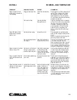
Water in system
Clogged condenser fins
Clean fins of all obstruc-
tions
The clogged fins in the condenser will
restrict air passage and reduce refrig-
erant capacity causing water down-
stream.
Fins should be periodically checked
and cleaned
Shortage of refrigerant
Fix the leak and add a
charge of refrigerant
Loss of refrigerant will cause improper
functioning.
A qualified refrigeration specialist
should perform the necessary repairs,
or factory should be contacted if the
units is in warranty
Refrigeration system is
not functioning
Double check if the
refrigerant compressor is
running
To check if the compressor is running,
check compressor-on light.
It is possible for the fan to be operat-
ing but not the compressor.
Compressor not running can be
caused by several factors. A qualified
refrigerant technician should check all
refrigerant and electrical controls
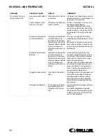
Excessive pressure dew
point
Readjust refrigerant
evaporating pressure
The refrigerant pressure adjustment
valve is identified by a label.
Turning the adjustment screw coun-
terclockwise will decrease the refrig-
erant pressure and lower the dew
point.
Adjust valves in ¼ turn increments to
allow 15 minutes for pressure stabili-
zation with full air flowing. Be sure that
gauge indicates that pressure stays in
green zone
High pressure drop
Excessive compressed
air flow or too low air inlet
pressure
Check actual pressure
and flow through the
dryer
This dryer is designed for a maximum
air flow. If too much air is pumped into
the dryer, water removal capacity may
not be sufficient, resulting in liquid
carryover downstream. Check the
rated output of the air compressor
Freeze up
Ensure that the operat-
ing room temperature is
above 41°F/5°C
Readjust refrigeration
controls
Frosting of the lines is an indication
that controls are set too low.
Controls may be adjusted in the field
by means of the hot gas bypass valve.
Turn the screw clockwise to increase
refrigerant pressure setting which will
increase pressure dew point.
Turn screw in ¼ turn increments until
frost disappears. Allow 15 minutes for
pressure stabilization with air flowing
Clogged heat exchanger Clean heat exchanger
with a reverse air flow
Dryers are supposed to be used with
compressed air free of any aggressive
contaminants. Some contaminants
and impurities may require a special
heat exchanger. Contact your dealer
with your application details.
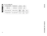
PROBLEM
POSSIBLE CAUSE
REPAIR
COMMENTS
Summary of Contents for RD Series
Page 8: ...8 NOTES ...
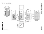
Page 18: ...RH SERIES HIGH TEMPERATURE SECTION 2 18 2 7 ED RH15 50 02250195 252 R00 ...
Page 20: ...RH SERIES HIGH TEMPERATURE SECTION 2 20 2 8 ED RH75 100 02250195 253 R00 ...
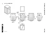
Page 22: ...RH SERIES HIGH TEMPERATURE SECTION 2 22 2 9 ID RH15 50 02250195 252 R00 ...
Page 24: ...RH SERIES HIGH TEMPERATURE SECTION 2 24 2 10 ID RH75 100 02250195 253 ...
Page 26: ...RH SERIES HIGH TEMPERATURE SECTION 2 26 2 11 P I RH15 75 02250195 284 ...
Page 28: ...RH SERIES HIGH TEMPERATURE SECTION 2 28 2 12 P I RH100 02250195 285 ...
Page 30: ...RH SERIES HIGH TEMPERATURE SECTION 2 30 2 13 WIRING DIAGRAM 02250195 303 R00 ...
Page 40: ...40 NOTES ...
Page 50: ...PRODUCT USER MANUAL SECTION 3 50 3 20 ED RN 5 15 02250195 257 R00 ...
Page 52: ...PRODUCT USER MANUAL SECTION 3 52 3 21 ED RN 25 02250195 258 R00 ...
Page 54: ...PRODUCT USER MANUAL SECTION 3 54 3 22 ED RN 35 50 02250195 259 R00 ...
Page 56: ...SECTION 3 PRODUCT USER MANUAL 56 3 23 ED RN 75 02250195 260 R00 ...
Page 58: ...SECTION 3 PRODUCT USER MANUAL 58 3 24 ED RN 100 02250195 260 R00 ...
Page 60: ...SECTION 3 PRODUCT USER MANUAL 60 3 25 ED RN 125 02250195 261 R00 ...
Page 62: ...SECTION 3 PRODUCT USER MANUAL 62 3 26 ED RN 150 02250195 262 R00 ...
Page 64: ...PRODUCT USER MANUAL SECTION 3 64 3 27 ED RN 175 02250195 263 R00 ...
Page 66: ...SECTION 3 PRODUCT USER MANUAL 66 3 28 ED RN 200 02250195 263 R00 ...
Page 68: ...PRODUCT USER MANUAL SECTION 3 68 3 29 ED RN 250 02250195 264 R00 ...
Page 70: ...SECTION 3 PRODUCT USER MANUAL 70 3 30 ED RN 325 230 02250195 264 R00 ...
Page 72: ...PRODUCT USER MANUAL SECTION 3 72 3 31 ED RN 325 460 02250195 264 R00 ...
Page 74: ...SECTION 3 PRODUCT USER MANUAL 74 3 32 ID RN5 15 02250195 257 R00 ...
Page 76: ...PRODUCT USER MANUAL SECTION 3 76 3 33 ID RN25 02250195 258 R00 ...
Page 78: ...PRODUCT USER MANUAL SECTION 3 78 3 34 ID RN35 50 02250195 259 R00 ...
Page 80: ...PRODUCT USER MANUAL SECTION 3 80 3 35 ID RN75 100 02250195 260 ...
Page 82: ...PRODUCT USER MANUAL SECTION 3 82 3 36 ID RN125 02250195 261 ...
Page 84: ...SECTION 3 PRODUCT USER MANUAL 84 3 37 ID RN150 02250195 262 ...
Page 86: ...SECTION 3 PRODUCT USER MANUAL 86 3 38 ID RN175 200 02250195 263 ...
Page 88: ...SECTION 3 PRODUCT USER MANUAL 88 3 39 ID RN250 400 02250195 264 ...
Page 90: ...SECTION 3 PRODUCT USER MANUAL 90 3 40 P I RN5 10 15 25 02250195 288 ...
Page 92: ...SECTION 3 PRODUCT USER MANUAL 92 3 41 P I RN35 75 02250195 289 ...
Page 94: ...SECTION 3 PRODUCT USER MANUAL 94 3 42 P I RN100 200 02250195 290 ...
Page 96: ...SECTION 3 PRODUCT USER MANUAL 96 3 43 P I RN250 325 02250195 291 ...
Page 97: ...PRODUCT USER MANUAL SECTION 3 97 3 44 P I RD400 500 700 850 02250195 293 ...
Page 98: ...SECTION 3 PRODUCT USER MANUAL 98 3 45 P I RD700 850 02250195 294 ...
Page 101: ...101 NOTES ...
Page 102: ...SECTION 3 PRODUCT USER MANUAL 102 3 48 WIRING DIAGRAM RN5 10 15 20 25 02250195 306 ...
Page 104: ...PRODUCT USER MANUAL SECTION 3 104 3 49 WIRING DIAGRAM RN35 50 75 100 02250195 307 ...
Page 106: ...PRODUCT USER MANUAL SECTION 3 106 3 50 WIRING DIAGRAM RN125 150 02250195 308 ...
Page 108: ...PRODUCT USER MANUAL SECTION 3 108 3 51 WIRING DIAGRAM RN175 02250195 309 ...
Page 110: ...PRODUCT USER MANUAL SECTION 3 110 3 52 WIRING DIAGRAM RN200 02250195 310 ...
Page 112: ...PRODUCT USER MANUAL SECTION 3 112 3 53 WIRING DIAGRAM RN250 325 02250195 311 ...
Page 114: ...PRODUCT USER MANUAL SECTION 3 114 3 54 WIRING DIAGRAM RN250 325 230 3 60 A 02250195 973 1 ...
Page 116: ...PRODUCT USER MANUAL SECTION 3 116 3 55 WIRING DIAGRAM RN250 325 230 3 60 A 02250195 973 2 ...
Page 122: ...PRODUCT USER MANUAL SECTION 3 122 3 58 CONTROL CIRCUIT RN250 325 02250195 306 ...
Page 124: ...PRODUCT USER MANUAL SECTION 3 124 3 59 POWER CIRCUIT RN250 325 02250195 306 ...
Page 143: ...SECTION 3 PRODUCT USER MANUAL 143 ...
Page 158: ...158 NOTES ...
Page 166: ...E 680 CONTROLLER FOR REFRIGERANT DRYERS SECTION 4 166 4 3 ED RD400 02250195 264 R00 ...
Page 168: ...E 680 CONTROLLER FOR REFRIGERANT DRYERS SECTION 4 168 4 4 ED RD500 02250195 266 R00 ...
Page 170: ...E 680 CONTROLLER FOR REFRIGERANT DRYERS SECTION 4 170 4 5 ED RD700 02250195 266 R00 ...
Page 174: ...E 680 CONTROLLER FOR REFRIGERANT DRYERS SECTION 4 174 4 7 ED RD850 02250195 266 R00 ...
Page 178: ...E 680 CONTROLLER FOR REFRIGERANT DRYERS SECTION 4 178 4 9 ED RD1000 02250195 266 R00 ...
Page 198: ...SECTION 4 E 680 CONTROLLER FOR REFRIGERANT DRYERS 198 4 19 ID RD400 02250195 264 ...
Page 199: ...SECTION 4 E 680 CONTROLLER FOR REFRIGERANT DRYERS 199 ...
Page 200: ...E 680 CONTROLLER FOR REFRIGERANT DRYERS SECTION 4 200 4 20 ID RD500 850 02250195 266 ...
Page 214: ...E 680 CONTROLLER FOR REFRIGERANT DRYERS SECTION 4 214 4 27 ID RD3800 AIR COOLED 02250195 270 ...
Page 218: ...E 680 CONTROLLER FOR REFRIGERANT DRYERS SECTION 4 218 4 29 P I RD400 02250195 291 ...
Page 220: ...E 680 CONTROLLER FOR REFRIGERANT DRYERS SECTION 4 220 4 30 P I RD500 850 02250195 293 ...
Page 222: ...E 680 CONTROLLER FOR REFRIGERANT DRYERS SECTION 4 222 4 31 P I RD700 850 02250195 294 ...
Page 224: ...E 680 CONTROLLER FOR REFRIGERANT DRYERS SECTION 4 224 4 32 P I RD1000 6000 02250195 297 ...
Page 226: ...E 680 CONTROLLER FOR REFRIGERANT DRYERS SECTION 4 226 4 33 P I RD1000 6000 02250195 298 ...
Page 266: ...266 NOTES ...
Page 267: ...NOTES 267 ...

