SECTION 2
RH SERIES—HIGH TEMPERATURE
15
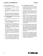
2.5
REFRIGERANT DRYER
FEATURES
2.5.1 C
OMPRESSOR
T
YPE
The High Temperature Inlet Refrigerated
compressed air dryers use the sealed Hermetic type
of compressors and require no periodic servicing.
2.5.2 C
ONDENSER
The air-cooled condenser is equipped with
helicoidally fans controlled by a pressure switch the
controls the fan cycling in order to maintain the
refrigerant high pressure at the correct level.
Air cooled aftercooler is integrated to the condenser.
The fan motor of the air cooled aftercooler is
separate and it only starts to function when the inlet
air temperature is equal or above 95°F. This is
controlled by a thermostatic switch.
2.5.3 R
EFRIGERANT
CIRCUIT
PROTECTION
O
VERLOAD
PROTECTOR
:
The single phase compressors are equipped with an
overload protector which is a thermal sensitive
switch controlling the temperature of the compressor
and overheating. In case of malfunction, the
protector trips out. However, it switches on again
automatically as soon as the compressor has cooled
down.
H
IGH
PRESSURE
SECURITY
SWITCH
:
Refrigerant circuits are protected against excessive
pressure by a security switch that stops the
compressor in case of too high a pressure. In case
this safety switch has tripped, it has to be manually
reset before switching on the dryer.
2.5.4 F
ILTER
DRYER
In order to keep the refrigerant circuit void of all
moisture, a filter drier is used in line. This filter also
traps any solid particles that may have migrated in
the circuit during operation. To avoid problems, the
refrigerant circuit must be vacuumed before filling it
with the recommended refrigerant.
2.5.5 R
EFRIGERANT
CIRCUIT
REGULATION
1. The evaporating pressure is kept constant
by controlled injection of hot gas from the
high-pressure side into the low-pressure
section of the circuit through a by-pass valve.
This constant pressure corresponds to a sta-
ble evaporating temperature adjusted as
close to 32°F as possible.
2. The liquid refrigerant is injected into the
evaporator through a thermostatic expansion
valve keeping the superheat of the refriger-
ant constant at the outlet of the evaporator.
3. The mix of hot gas from by-pass valve and
cold gas from evaporator is called superheat.
2.5.6 C
ONDENSATE
DRAIN
—
TRAP
ASSEMBLY
Disassembling the drain is easy because it can be
isolated from the air circuit under pressure with a ball
valve. The drain has to be isolated before being
dismantled.
Summary of Contents for RD Series
Page 8: ...8 NOTES ...
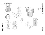
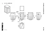
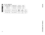
Page 18: ...RH SERIES HIGH TEMPERATURE SECTION 2 18 2 7 ED RH15 50 02250195 252 R00 ...
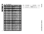
Page 20: ...RH SERIES HIGH TEMPERATURE SECTION 2 20 2 8 ED RH75 100 02250195 253 R00 ...
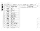
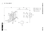
Page 22: ...RH SERIES HIGH TEMPERATURE SECTION 2 22 2 9 ID RH15 50 02250195 252 R00 ...
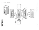
Page 24: ...RH SERIES HIGH TEMPERATURE SECTION 2 24 2 10 ID RH75 100 02250195 253 ...
Page 26: ...RH SERIES HIGH TEMPERATURE SECTION 2 26 2 11 P I RH15 75 02250195 284 ...
Page 28: ...RH SERIES HIGH TEMPERATURE SECTION 2 28 2 12 P I RH100 02250195 285 ...
Page 30: ...RH SERIES HIGH TEMPERATURE SECTION 2 30 2 13 WIRING DIAGRAM 02250195 303 R00 ...
Page 40: ...40 NOTES ...
Page 50: ...PRODUCT USER MANUAL SECTION 3 50 3 20 ED RN 5 15 02250195 257 R00 ...
Page 52: ...PRODUCT USER MANUAL SECTION 3 52 3 21 ED RN 25 02250195 258 R00 ...
Page 54: ...PRODUCT USER MANUAL SECTION 3 54 3 22 ED RN 35 50 02250195 259 R00 ...
Page 56: ...SECTION 3 PRODUCT USER MANUAL 56 3 23 ED RN 75 02250195 260 R00 ...
Page 58: ...SECTION 3 PRODUCT USER MANUAL 58 3 24 ED RN 100 02250195 260 R00 ...
Page 60: ...SECTION 3 PRODUCT USER MANUAL 60 3 25 ED RN 125 02250195 261 R00 ...
Page 62: ...SECTION 3 PRODUCT USER MANUAL 62 3 26 ED RN 150 02250195 262 R00 ...
Page 64: ...PRODUCT USER MANUAL SECTION 3 64 3 27 ED RN 175 02250195 263 R00 ...
Page 66: ...SECTION 3 PRODUCT USER MANUAL 66 3 28 ED RN 200 02250195 263 R00 ...
Page 68: ...PRODUCT USER MANUAL SECTION 3 68 3 29 ED RN 250 02250195 264 R00 ...
Page 70: ...SECTION 3 PRODUCT USER MANUAL 70 3 30 ED RN 325 230 02250195 264 R00 ...
Page 72: ...PRODUCT USER MANUAL SECTION 3 72 3 31 ED RN 325 460 02250195 264 R00 ...
Page 74: ...SECTION 3 PRODUCT USER MANUAL 74 3 32 ID RN5 15 02250195 257 R00 ...
Page 76: ...PRODUCT USER MANUAL SECTION 3 76 3 33 ID RN25 02250195 258 R00 ...
Page 78: ...PRODUCT USER MANUAL SECTION 3 78 3 34 ID RN35 50 02250195 259 R00 ...
Page 80: ...PRODUCT USER MANUAL SECTION 3 80 3 35 ID RN75 100 02250195 260 ...
Page 82: ...PRODUCT USER MANUAL SECTION 3 82 3 36 ID RN125 02250195 261 ...
Page 84: ...SECTION 3 PRODUCT USER MANUAL 84 3 37 ID RN150 02250195 262 ...
Page 86: ...SECTION 3 PRODUCT USER MANUAL 86 3 38 ID RN175 200 02250195 263 ...
Page 88: ...SECTION 3 PRODUCT USER MANUAL 88 3 39 ID RN250 400 02250195 264 ...
Page 90: ...SECTION 3 PRODUCT USER MANUAL 90 3 40 P I RN5 10 15 25 02250195 288 ...
Page 92: ...SECTION 3 PRODUCT USER MANUAL 92 3 41 P I RN35 75 02250195 289 ...
Page 94: ...SECTION 3 PRODUCT USER MANUAL 94 3 42 P I RN100 200 02250195 290 ...
Page 96: ...SECTION 3 PRODUCT USER MANUAL 96 3 43 P I RN250 325 02250195 291 ...
Page 97: ...PRODUCT USER MANUAL SECTION 3 97 3 44 P I RD400 500 700 850 02250195 293 ...
Page 98: ...SECTION 3 PRODUCT USER MANUAL 98 3 45 P I RD700 850 02250195 294 ...
Page 101: ...101 NOTES ...
Page 102: ...SECTION 3 PRODUCT USER MANUAL 102 3 48 WIRING DIAGRAM RN5 10 15 20 25 02250195 306 ...
Page 104: ...PRODUCT USER MANUAL SECTION 3 104 3 49 WIRING DIAGRAM RN35 50 75 100 02250195 307 ...
Page 106: ...PRODUCT USER MANUAL SECTION 3 106 3 50 WIRING DIAGRAM RN125 150 02250195 308 ...
Page 108: ...PRODUCT USER MANUAL SECTION 3 108 3 51 WIRING DIAGRAM RN175 02250195 309 ...
Page 110: ...PRODUCT USER MANUAL SECTION 3 110 3 52 WIRING DIAGRAM RN200 02250195 310 ...
Page 112: ...PRODUCT USER MANUAL SECTION 3 112 3 53 WIRING DIAGRAM RN250 325 02250195 311 ...
Page 114: ...PRODUCT USER MANUAL SECTION 3 114 3 54 WIRING DIAGRAM RN250 325 230 3 60 A 02250195 973 1 ...
Page 116: ...PRODUCT USER MANUAL SECTION 3 116 3 55 WIRING DIAGRAM RN250 325 230 3 60 A 02250195 973 2 ...
Page 122: ...PRODUCT USER MANUAL SECTION 3 122 3 58 CONTROL CIRCUIT RN250 325 02250195 306 ...
Page 124: ...PRODUCT USER MANUAL SECTION 3 124 3 59 POWER CIRCUIT RN250 325 02250195 306 ...
Page 143: ...SECTION 3 PRODUCT USER MANUAL 143 ...
Page 158: ...158 NOTES ...
Page 166: ...E 680 CONTROLLER FOR REFRIGERANT DRYERS SECTION 4 166 4 3 ED RD400 02250195 264 R00 ...
Page 168: ...E 680 CONTROLLER FOR REFRIGERANT DRYERS SECTION 4 168 4 4 ED RD500 02250195 266 R00 ...
Page 170: ...E 680 CONTROLLER FOR REFRIGERANT DRYERS SECTION 4 170 4 5 ED RD700 02250195 266 R00 ...
Page 174: ...E 680 CONTROLLER FOR REFRIGERANT DRYERS SECTION 4 174 4 7 ED RD850 02250195 266 R00 ...
Page 178: ...E 680 CONTROLLER FOR REFRIGERANT DRYERS SECTION 4 178 4 9 ED RD1000 02250195 266 R00 ...
Page 198: ...SECTION 4 E 680 CONTROLLER FOR REFRIGERANT DRYERS 198 4 19 ID RD400 02250195 264 ...
Page 199: ...SECTION 4 E 680 CONTROLLER FOR REFRIGERANT DRYERS 199 ...
Page 200: ...E 680 CONTROLLER FOR REFRIGERANT DRYERS SECTION 4 200 4 20 ID RD500 850 02250195 266 ...
Page 214: ...E 680 CONTROLLER FOR REFRIGERANT DRYERS SECTION 4 214 4 27 ID RD3800 AIR COOLED 02250195 270 ...
Page 218: ...E 680 CONTROLLER FOR REFRIGERANT DRYERS SECTION 4 218 4 29 P I RD400 02250195 291 ...
Page 220: ...E 680 CONTROLLER FOR REFRIGERANT DRYERS SECTION 4 220 4 30 P I RD500 850 02250195 293 ...
Page 222: ...E 680 CONTROLLER FOR REFRIGERANT DRYERS SECTION 4 222 4 31 P I RD700 850 02250195 294 ...
Page 224: ...E 680 CONTROLLER FOR REFRIGERANT DRYERS SECTION 4 224 4 32 P I RD1000 6000 02250195 297 ...
Page 226: ...E 680 CONTROLLER FOR REFRIGERANT DRYERS SECTION 4 226 4 33 P I RD1000 6000 02250195 298 ...
Page 266: ...266 NOTES ...
Page 267: ...NOTES 267 ...


