2.4 COMPRESSOR COOLING AND
LUBRICATION SYSTEM,
FUNCTIONAL DESCRIPTION
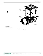
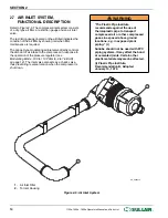
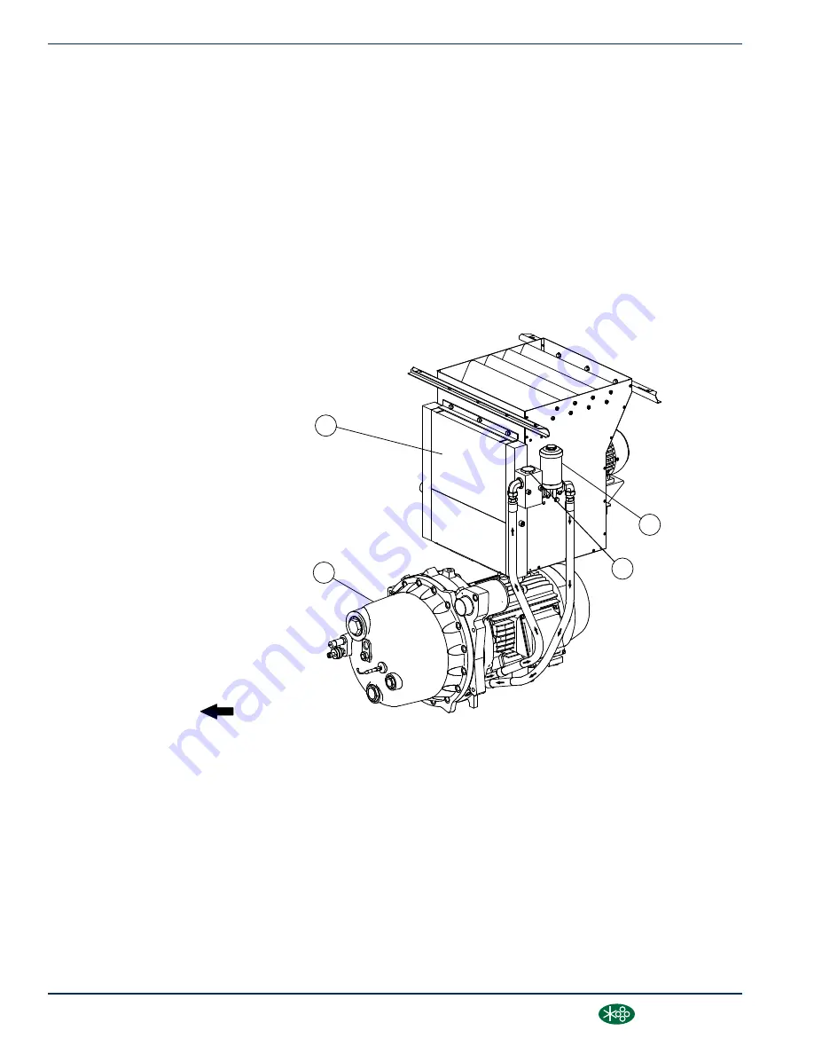
Refer to Figure 2-2. The Cooling and Lubrication System
consists of a fan, fan motor, radiator-type aftercooler/fluid
cooler, full flow fluid filter, thermal valve, and
interconnecting hoses. The pressure in the receiver tank
causes fluid flow by forcing the fluid from the high pressure
area of the receiver tank to an area of lower pressure in the
compressor unit.
Fluid flows from the bottom of the receiver tank to the
thermal valve. The thermal valve is fully open when the
fluid temperature is below 185˚F (85˚C). The fluid passes
through the thermal valve, the main filter and directly to the
compressor unit where it lubricates, cools and seals the
rotors and the compression chamber.
As the discharge temperature rises above 185˚F (85˚C),
due to the heat of compression, the thermal valve begins
to close and a portion of the fluid then flows through the
cooler. From the cooler the fluid flows to the fluid filter and
then on to the compressor unit.
A portion of the fluid flowing to the compressor is routed to
the anti-friction bearings which support the rotors inside
the compressor unit.
The fluid filter has a replacement element and an integral
pressure bypass valve. A message on the controller
indicates when the fluid filter needs to be changed.
FLUID
SU_0000083
1
2
3
4
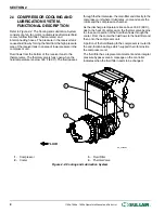
1. Compressor
2. Cooler
3. Fluid Filter
4. Thermal Valve
Figure 2-2: Cooling and Lubrication System
SECTION 2
8
1100e, 1500e, 1800e Operator’s Manual and Parts List
®
SULLAIR
®
Summary of Contents for 1107e
Page 101: ...THIS PAGE INTENTIONALLY LEFT BLANK...


