AB-26
AIRBAG SYSTEM
Disposal of Airbag Module (Deploying After Removal from Vehicle)
12.Disposal of Airbag Module
(Deploying After Removal
from Vehicle)
A: OPERATION
CAUTION:
• Do not discard an undeployed airbag module
because it may cause serious personal injury
when accidentally deployed.
• As a rule, the airbag module should be de-
ployed while still installed in the vehicle. Do not
remove the airbag modules unless necessary.
• Deployment of the airbag module should be
done on a flat place free from any possible dan-
ger. Avoid deploying outdoors during rainy or
windy weather.
• Do not damage the airbag module or drop it.
• Deploying the airbag module causes a high
explosive noise, be sure to warn people in the
area, and do not allow anyone within a 5 m (16
ft) radius of the disposal site.
• Some smoke will be emitted from deployment
of the airbag module. Therefore, it must be de-
ployed in a well ventilated place with no smoke
detector nearby.
• Wear protective gloves, safety goggles and
earplugs during this operation. Wash your
hands afterwards.
• After deployment, the airbag module will be
especially hot, leave it unattended for 40 min-
utes, and then discard it.
• Do not let water get on the deployed airbag
module.
• Wrap the deployed airbag module in an air-
tight vinyl bag, and discard it.
• If circumstances do not permit the airbag
module deployment, contact the SUBARU deal-
er.
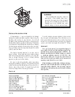
1. DRIVER’S AIRBAG MODULE
1) Turn the ignition switch to OFF.
2) Disconnect the ground cable from battery and
wait for at least 20 seconds before starting work.
3) Remove the driver’s airbag module. <Ref. to AB-
14, Driver’s Airbag Module.>
4) Install the removed bolts to airbag module.
5) Bundle three automotive wire harnesses [each
with a sectional area of 1.25 mm
2
(0.00194 sq in) or
more], and bind them twofold around airbag mod-
ule stay.
6) Short the terminal to alligator clip furnished as
deployment tool (A).
7) Connect the deployment tool and deployment
adapter D (B).
CAUTION:
The deployment tool should be kept shorted
terminals until just before deployment of airbag
module.
8) Connect the deployment adapter D connector to
airbag module.
(A) Deployment tool:
(Tool number 98299PA030)
(B) Deployment adapter D:
(Tool number 98299SA010)
AB-00780
AB-00048
SB-00021
(A)
(B)
Summary of Contents for 2004 Forester
Page 54: ...AC 52 HVAC SYSTEM HEATER VENTILATOR AND A C General Diagnostics ...
Page 96: ...AC 42 HVAC SYSTEM AUTO A C DIAGNOSTIC General Diagnostic Table ...
Page 306: ...ET 10 ENTERTAINMENT Front Accessory Power Supply Socket ...
Page 312: ...COM 6 COMMUNICATION SYSTEM Horn Switch ...
Page 347: ...BODY STRUCTURE BS Page 1 General Description 2 2 Datum Points 3 3 Datum Dimensions 11 ...
Page 356: ...BS 10 BODY STRUCTURE Datum Points 61 BS 00030 66 62 63 BS 00031 64 BS 00032 ...
Page 380: ...IDI 18 INSTRUMENTATION DRIVER INFO Ambient Sensor ...
Page 381: ...SEAT SE Page 1 General Description 2 2 Front Seat 6 3 Rear Seat 13 ...
Page 436: ...SL 42 SECURITY AND LOCK Keyless Transmitter ...
Page 446: ...SR 10 SUNROOF T TOP CONVERTIBLE TOP SUNROOF Sunroof Switch ...
Page 456: ...EI 10 EXTERIOR INTERIOR TRIM General Description 12 REAR GATE TRIM EI 00012 ...
Page 532: ...CC 14 CRUISE CONTROL SYSTEM Neutral Position Switch MT model ...
Page 571: ...CRUISE CONTROL SYSTEM DIAGNOSTIC CC H4DOTC Page 1 General Description 2 ...


