background image

16

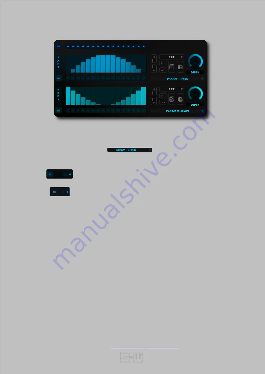
TAP EDIT (FX) PAGE 2

Tap Edit Page 2 can control up to two individual post delay FX parameters.
If a parameter is set in the PARAM1/2 menu

the actual POST FX becomes a POST 'TAP' FX

which  provides  individual  values  for

each

  tap  of  the  selected  POST  FX  parameter.  Since  each  tap  uses  its  own  FX

instance this can become CPU expensive if used extensively.

Modulation

(

if a modulation source is set at the FX Page

), as well as

FX activation

can be enabled or disabled for each tap individually. 

Note: Right click into a Mod[M] or Active[ON] button row toggles all boxes enabled or disabled.

All other control elements on this page share the same functionality as on TAP EDIT PAGE 1.

©

 2020-2021

 Stefan Weyel 

www.stw-audio.com


[email protected]


doc version 1.2.0

Summary of Contents for AUDIO REFLEX-PRO-X

Page 1: ...d input routings 3 effect slots for each channel 4 delay modes 22 selected customizable effects with countless combination possibilities Extensive modulation options 10 modulation sources of three dif...

Page 2: ...ETTINGS 8 MASTER EFFECT 8 MASTER SETTINGS 10 FEEDBACK MATRIX 11 DELAY MODES 11 TAP EDIT PAGE 15 DSP EFFECTS 17 PRE POST EFFECTS 17 FEEDBACK EFFECTS 26 LFO 27 ARPEGGIATOR TRANCEGATE 28 ENVELOPE GENERAT...

Page 3: ...stration name and a serial number into the corresponding fields Both are sent to you in a registration doc after purchasing REFLEX PRO X Though it s not recommended you can enter the data manually Mor...

Page 4: ...EFLEX PRO X instance Beside applying just a visual preference different colour settings could come in handy to distinguish multiple instances of REFLEX PRO X in the same project A preview of the appli...

Page 5: ...lots with identical parameter selections All described parameters for the MAIN DELAY and EFFECT SECTIONS as well as the SLOT SETTINGS are available for each slot _______________________________ MAIN S...

Page 6: ...n FB FX Post Delay Effect Section POST FX Slot Settings SLOT Low Frequency Oscillators LFO Arpeggiator TranceGate GATE Envelope Generator ENV Modulation Logic LOGIC Clicking on displayed circles activ...

Page 7: ...stered with a valid license key VALUE The value of the last used parameter Note This display shows REGISTER until REFLEX PRO X is registered with a valid license key You can enter the registration dis...

Page 8: ...uts L R R L X X Muting the output can be a simple way of 100 wet routing through the MasterFX section e g EQs _______________________________ MASTER EFFECT EFFECT SELECTOR Drop down Menu for the maste...

Page 9: ...ing type at 500Hz 18dB 18dB MID FREQ Center Frequency of the mid band 500Hz 5000Hz MODULATION Gain of the Mid band 18dB 18dB HISHELF Gain of the Hi band shelving type at 3000Hz 18dB 18dB 2 BAND EQ TWO...

Page 10: ...takes the sum of all four slots as input and sends it to the WET control Modes are Off Slow 1 Original Mode Slow 2 Fast BOOST Input Gain of the master limiter 0 36dB SEND Mutes the dry amount of the a...

Page 11: ...are all relative to the Main Feedback level in the MAIN SECTION of the appropriate slot 100 100 _______________________________ DELAY MODES The delay section provides a stereo delay module with four d...

Page 12: ...PING PONG Same as LEFT PING PONG just with the mono input signal RIGHT PING PONG Right input goes into right input and is feed back into the left channel Left feedback goes into the right channel afte...

Page 13: ...nd is read from the buffer head in reverse The first input sample is therefore reached after 2 16th So the attack of a percussive sound will be heard at the doubled amount of the selected delay time P...

Page 14: ...Only left delay taps are routed to a mono out RIGHT MONO Only right delay taps are routed to a mono out TAP EDIT Opens the Tap Edit Page Closes the Tap Edit Page EDIT PAGE Toggles TIME LEVEL PAN and...

Page 15: ...menu A selected step amount enables a step grid for fixed slider divisions TAP EDIT PAGE 1 NUDGE LEFT Moves all sliders one step left NUDGE RIGHT Moves all sliders one step right SET Drop down menu to...

Page 16: ...ap uses its own FX instance this can become CPU expensive if used extensively Modulation if a modulation source is set at the FX Page as well as FX activation can be enabled or disabled for each tap i...

Page 17: ...ng on an empty rectangle closes the effect selector and leaves your settings unchanged _______________________________ PRE POST EFFECTS A collection of 15 different effects could be invoked in the pre...

Page 18: ...tor signal 0Hz 2000Hz SHAPE Shape of the modulating wave Greater values produce more overtones 0 100 WIDTH Amount of signal phase to panorama 0 100 SPREAD Frequency spread factor of left right channel...

Page 19: ...ning width of left and right channel 100 results in right channel on left output left channel on right output 0 results to mono signal of both channels 100 results in right channel on right output lef...

Page 20: ...ft right channel 100 100 LOFI II Lofi algorithm collection DRIVE Gain amount 0 100 NOISE Noise amount 0 100 DNSAMPLE Downsampling amount 0 100 BITCRUSH Bitcrush amount 0 100 WAVE SHAPE with Bandpass F...

Page 21: ...b Octave LOPASS HIPASS Filter FREQ Cutoff frequency of the Chebychev filter 50Hz 20kHz Q Q Resonance amount 0 100 SPREAD Cutoff frequency spread factor of left right channel 100 100 MODE Filter type A...

Page 22: ...cy of the Hi pass filter 50Hz 20kHz HP SLOPE Hi pass Filter slope 12 24 36 and 48 dB Octave FREQ LP Cutoff frequency of the Lo pass filter 50Hz 20kHz LP SLOPE Lo pass Filter slope 12 24 36 and 48 dB O...

Page 23: ...FORWARD BACKWARD mode 50Hz 20kHz LOPASS Cutoff frequency of the outputs Lo pass filter FORWARD BACKWARD mode 50Hz 20kHz SPREAD Cutoff frequency spread factor of left right channel 100 100 VOWEL Filte...

Page 24: ...s share the enable disable button Most effects also share the MIX parameter which sets the ratio of dry wet signal in the range from 0 100 These are not further explained in the individual effect desc...

Page 25: ...ations WAVE Select the LFO wave either from the drop down menu by clicking into the wave display or with the left or right arrows to step through the waves INVERT Inverts the wave top bottom REVERSE R...

Page 26: ...s LENGTH Click on a top row number sets the amount of steps Inactive steps are greyed out LEVEL Drawing into the bar area moves the step values between 0 or 100 to 100 depending on the polarity settin...

Page 27: ...envelope settings Be careful with high GAIN settings GAIN Gain of the envelope input signal 0dB 40dB LOCUT Cutoff frequency of the envelope input Hi pass filter 50Hz 10kHz HICUT Cutoff frequency of t...

Page 28: ...2 0 3 MULTIPLY Output of Source1 and Source2 are multiplied 0 5 0 2 0 25 MIN The minimum value of both sources 0 5 0 2 0 5 MAX The maximum value of both sources 0 5 0 2 0 2 ABS MIN The absolute minimu...

Reviews: