Studer Vista 5 M2 User Manual Download Page 9

Vista 5 M2 Digital Mixing System

TFT Meters  9

Date printed: 09.06.11

SW V4.5

Fader Bay Meters


  The default assignment of the TFT meters to the fader channel strips is 1:1. 

This may be modified by the system administrator only; if not logged in as 

system administrator, the ‘Fader Bay Meters’ tab is not displayed, and meter 

assignment is is restricted to the control bay. 


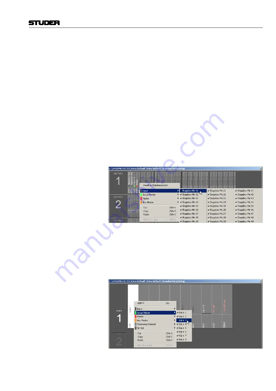
  Assignment is done in the strip setup window. First, click the ‘Fader Bay 

Meters’ tab. The window changes to the view shown below. Entering channels 

is done with the same mechanism as is used for the assignment of channels 

to bays.


  Changes in the channel assignment may be easily reset to the default setting 

by selecting ‘Reset to StripAssignment’.


Lower Meter Area

  The default settings of the lower meter area are labeled ‘DEF’. These are the 

history view for mono and stereo channels, and the surround view for 5.1 

channels. 


  When right-clicking into the lower meter area, the display mode of the lower 

part of the meter can be selected (‘HIST’ for the history display, ‘BUS’ for 

bus assignment view, ‘SRND’ for surround view, and ‘L2’ for layer 2 view). 

Options not available for a particular channel type will be grayed-out.


  Changes made here may also be reset to the default setting by selecting ‘Reset 

to StripAssignment’ after a right-click in the upper meter area.


Control Bay Meters


  Click on the ‘Control Bay Meters’ tab. The window changes to the view shown 

below. Entering channels is done with the same mechanism as is used for the 

assignment of channels to bays. 


  After selecting one of the ‘USER’ fields, the view corresponding to the user 

keys can be defined. 


  Please note that the two meters at the far right of the control bay are 

always 

used for PFL and CR monitoring and cannot be assigned to a channel.


Summary of Contents for Vista 5 M2

Page 1: ...5 VISTA 5 M2 SW V4 5 DIFFERENCES AND NEW FEATURES Please insert this document at the end of chapter 10 of your Vista 5 operating instructions folder Meterbridge Installation Option 3 Mechanical 3 Electrical 4 Configuration 4 System Start 4 TFT Level Meters 5 TFT Meter Setup 8 ...

Page 2: ...Vista 5 M2 Digital Mixing System 2 TFT Meters Date printed 09 06 11 SW V4 5 ...

Page 3: ...ed since one of the meterbridge screens is provided for this purpose Remove the 6 countersunk head screws at the rear of the console marked in red in the picture below Use a 2 5 mm Allen key These screws will no more be used 32 fader console 42 fader console VGA SECONDARY LAN PRIMARY LAN GRAPHICAL CONTROLLER SCREEN VGA DVI CUSTOM PANEL GPIO COM1 RS422 COM2 RS422 DATA USB 12 24V DIN MIDI IN MIDI OU...

Page 4: ...condary Lan Port to Meterbridge Switch Meterbridge PC to Meterbridge Switch GC DVI Signal to Meterbridge Meterbridge PC Bottom View Ext DVI Input Power ON GC DVI Input Power ON GC DVI Input Ethernet Ethernet USB Power On Link to Meterbridge PC Cat5 Ethernet Connection Cat5 MADI Connection DVI Connection Power On Connection Configuration For correct operation of the TFT meters open the D950system i...

Page 5: ...ormation a lower area is configurable that enables displaying different options depending on the channel type It can bring a surround image view or what is called the history diagram of incoming or outgoing signal waveforms This shows the history of the signal and makes it easy to spot anomalies in the audio signal such as overloads or signal loss When focusing on some important channels one might...

Page 6: ...on meter on top of the meter bars both on stereo inputs as well as on stereo master channels Above the level bargraph area gain reduction meters are added Clipping is displayed by turning the white bargraph section i e the segments above the headroom threshold over to red The meter tap point can be selected from input post fader and direct output level of the corresponding channel It is possible t...

Page 7: ...ñ shift key allow switching between different views All VIEW keys are of the momentary latching type The FOLLOW key displays the metering that belongs to the channel assigned to the desk surface Then there are view keys for all different type of master channels Aux Groups program Masters Matrix etc as well as output meter views of multitrack and n 1 x busses Moreover there are four user keys that ...

Page 8: ...in the strip setup window that is a slow indication of signal activity at this channel s input Color is used to identify the channel s status A blue meter bar means that the channel has its fader open and is switched on If the meter bar is gray then the channel has a signal associated with it but either the channel fader is closed or the channel is muted off If the meter bar is red the channel cur...

Page 9: ...labeled DEF These are the history view for mono and stereo channels and the surround view for 5 1 channels When right clicking into the lower meter area the display mode of the lower part of the meter can be selected HIST for the history display BUS for bus assignment view SRND for surround view and L2 for layer 2 view Options not available for a particular channel type will be grayed out Changes ...

Page 10: ...Vista 5 M2 Digital Mixing System 10 TFT Meters Date printed 09 06 11 SW V4 5 ...

Reviews: