background image

- 11 -

Cont ...

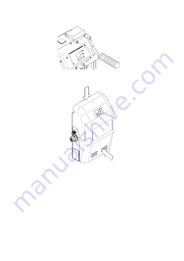
5.  Retain the SPU Mini to the wall mounting plate using the single M6  


retaining screw at the top of the wall plate.

6.  Fit the plastic cover by pressing as indicated below with the palm of the    


hand as until the Dual Lock

TM

 is heard to ‘click’.

Fig. 6

Fig. 7

Summary of Contents for Stuart SPU 130 Mini

Page 1: ...booklet with the end user as it contains important guarantee maintenance and safety information Read this manual carefully before commencing installation This manual covers the following products SPU...

Page 2: ...l applications These could include slight leaks air venting etc The units are not designed to deal with sudden losses of system pressure due to major water losses over extended periods They are also n...

Page 3: ...th the appliance z z This product should not be used for the supply of water to more than one heating cooling system at a time z z The electrical installation must be carried out in accordance with th...

Page 4: ...allation details carefully as they are intended to ensure this product provides long trouble free service Failure to install the unit in accordance with the installation instructions will lead to inva...

Page 5: ...used with item C 1 Flexible hose G 15 mm compression 1 Cable tie 2 M6 screw 1 Instruction book 1 Wall mounting plate 1 A E C B D H G F I Fig 1 IMPORTANT With the appliance removed from its packaging...

Page 6: ...d to inlet and outlet branches of the unit Do not secure pipework to the SPU Mini this will cause damage and possible leakage 1 17 Flux Solder joints must be completed and flux residues removed prior...

Page 7: ...and view the display 2 13 Protection The SPU Mini must be located in a dry frost free area 2 14 Ventilation Ensure an adequate air flow to cool the SPU Mini Separate the SPU Mini from other appliance...

Page 8: ...to the appliance outlet However care must be taken when mounting the SPU Mini that any noise is not amplified through loose panels or pipework 2 21 Flexible hose Only use the Stuart Turner hose suppl...

Page 9: ...y access 3 12 Principle of operation The pressurisation unit consists of a break tank and one or two piston pumps The break tank is supplied with mains water from the left to a float valve and include...

Page 10: ...n the tank is not rotated If the valve is rotated it may not function correctly with the risk of flooding Do not overtighten 4 13 Wall plate fixing 1 When installing the SPU Mini on a wall ensure suit...

Page 11: ...i to the wall mounting plate using the single M6 retaining screw at the top of the wall plate 6 Fit the plastic cover by pressing as indicated below with the palm of the hand as until the Dual LockTM...

Page 12: ...xible hoses to allow the unit to be isolated if required The isolation valve on the outlet should be of a lockshield type See Fig 10 3 A drain valve must be fitted on the outlet of the SPU Mini before...

Page 13: ...the heating cooling system These devices will prevent the pressure sensor from reading the system pressure and will lead to incorrect operation of the unit 9 The SPU Mini should be connected to the s...

Page 14: ...ed with earthing clamps in accordance with current regulations Fig 12 5 16 Earthing This appliance must be earthed via the supply cord 5 17 Pipework Copper or metallic pipework must have supplementary...

Page 15: ...blue must be connected to the terminal which is marked with the letter N or coloured black z z The wire which is coloured brown must be connected to the terminal which is marked with the letter L or...

Page 16: ...protect the SPU Mini from damage For connection of output relays follow the steps and images below 1 Remove the required green connector from the right hand side of the control board 2 Strip 6 8 mm in...

Page 17: ...ance of this internal wiring all cable routing and securing details are carefully noted to ensure re assembly to the same factory pattern is always maintained If the supply cord is to be changed or is...

Page 18: ...l system design pressure 6 13 Prior to commissioning fill the heating cooling system via a filling loop The SPU Mini is NOT designed to fill the system from empty it is only intended to top up the sys...

Page 19: ...ed whilst the unit is powered If an alarm or error is raised the red Error light will be displayed A number pressure set points can be set using the menus these set points are detailed below 1 to 4 an...

Page 20: ...reverts to normal operation This operation will save the changed values P1 System pressure 2 see Fig 18 Sets the required system pressure Set in 0 1 bar increments up to the maximum set value for the...

Page 21: ...z z Ensure both inlet and outlet hydraulic connections are made and watertight z z Turn on water supply to SPU Check for leakage and operation of fill valve z z Allow the tank to fill and water level...

Page 22: ...re for the Hi Lo alarms please ensure that the normal system pressure fluctuations are below the Hi pressure alarm setting and above the differential pressure If this is not done the SPU will try to c...

Page 23: ...hAssist on 44 0 800 31 969 80 8 14 Long term isolation and restart procedure If the system is to be shut down for an extended period of time due to maintainance or system modifications being carried o...

Page 24: ...leakage 6 Open the drain valve on the outlet of the SPU Mini 7 Turn on the mains electrical power and ensure both if fitted pumps can run use test pump option P6 if needed and are pumping water to dr...

Page 25: ...6 bar Ambient air temperature Min 4 o C Max 40 o C Relative humidity 95 non condensing Min Max water temperature Min 4 o C Max 23 o C Water tank Usable capacity 2 litres Inlet valve and fill rate Torb...

Page 26: ...ed Low pressure Leak in system Check system for leaks Check for leaking pressure relief valve Low pressure alarm set too high Reduce Low press alarm pressure Check system pressure range during normal...

Page 27: ...sioned Company Engineer System set pressure Differential pressure Hi alarm set pressure Lo alarm set pressure 12 14 Service Log Service No 1 Date Engineer name Company name Tel No System pressure bar...

Page 28: ...ation Float valve operation x Level probe operation x Water condition x Exp vessel pre charge x Comments Service No 3 Date Engineer name Company name Tel No System pressure bar Differential pressure b...

Page 29: ...ation Float valve operation x Level probe operation x Water condition x Exp vessel pre charge x Comments Service No 5 Date Engineer name Company name Tel No System pressure bar Differential pressure b...

Page 30: ...lation improper use unauthorised repair normal wear and tear and defects which have a negligible effect on the value or operation of the product Reasonable evidence must be supplied that the product h...

Page 31: ...31...

Page 32: ...S EN 61000 4 3 BS EN 61000 4 4 BS EN 61000 4 5 BS EN 61000 4 6 BS EN 61000 4 11 BS EN 61000 6 1 BS EN 61000 6 3 EMF Directive 1999 519 EC BS EN 62233 RoHs Directive 2011 65 EU WEEE Directive 2012 19 E...

Reviews: