Stuart Turner Flomate iBoost 46668 Installation, Operation & Maintanance Instructions Download Page 12

- 12 -

5  ELECTRICAL INSTALLATION / EARTHING

5.11

 Regulations:

 The electrical installation must be carried out in  


accordance with the current national electrical regulations and  


installed by a qualified person.

5.12

 Safety:

 In the interests of electrical safety a 30 mA residual current    


device (

R.C.D. not supplied

) should be installed in the supply circuit.  


This may be part of a consumer unit or a separate unit.

5.13  Before starting work on the electrical supply ensure power supply is   
 isolated.
5.14

  DO NOT

 allow the supply cord to contact hot surfaces, including the    


motor shell, pump body or pipework.  The cord should be safely routed  


and secured by cable clips.
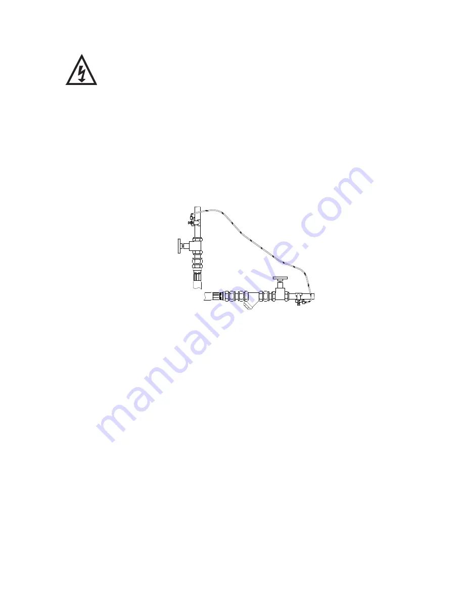
5.15

  Adjacent pipes:

 Adjacent suction and delivery pipes should be fitted with  


earthing clamps in accordance with current regulations (Fig. 9).

5.16

 Earthing:

 This appliance must be earthed via the supply cord, which must be    


correctly connected to the earth point located in the terminal box.

5.17 

Pipework:

  Copper or metallic pipework must have supplementary earth  


bonding where the continuity has been broken by flexible hoses or plastic  


 components.
5.18

  Additional earthing:

 Certain installations may require additional earthing  


arrangements such as equipotential bonding.  Reference should be made to the  


relevant regulations concerning this subject to ensure compliance.

5.19

 Connections:

 The pump must be permanently connected to the fixed wiring of   


the mains supply using the factory fitted supply cord, via a double pole  


switched (with a minimum of 3 mm contact separation) fused spur off    


the ring main and 

NOT

 connected to the boiler or the immersion heater circuits.

5.20  The electrical connection 

must be

 made adjacent to (not behind) the iBoost to    


allow disconnection of the electrical supply should the pump module need to be  


removed for service or maintenance.

Diagram of 
earth continuity 
connections

Fig. 9

Summary of Contents for Flomate iBoost 46668

Page 1: ...instruction booklet with the home owner as it contains important guarantee maintenance and safety information Read this manual carefully before commencing installation This manual covers the followin...

Page 2: ...ldren aged from 8 years and above and persons with reduced physical sensory or mental capabilities or lack of experience and knowledge if they have been given supervision or instruction concerning use...

Page 3: ...4 Important Facts read before commencing installation 5 Location 6 Key Features 7 Installation Pump Connections 8 Electrical Installation 12 Commissioning 15 Maintenance 17 Technical Specification 19...

Page 4: ...ve Item Description Qty Item Description Qty Flomate iBoost CAT 5 1 M6 screw 1 Hose sealing washer 1 Instruction book 1 Retaining strap 1 Installation template 1 A E C B D F Fig 1 IMPORTANT With the a...

Page 5: ...ost this will cause damage and possible leakage 1 17 Flux Solder joints must be completed and flux residues removed prior to iBoost installation flux damage will void any warranty 1 18 Pipework design...

Page 6: ...rmance outlet pipework must be 22 mm pipe Pipework should only reduce to 15 mm when entering terminal fittings 2 19 Static outlet pressure The static outlet head must also be within the maximum requir...

Page 7: ...Drain valve Tank Tank access cover Mains water connection User interface User interface cable Pump module Pump module retaining screws Pump isolation valve behind pump Note iBoost CAT 5 shown with fro...

Page 8: ...Water outlet pipework 1 The pump has a G threaded connection to accept the supplied hose The hose is made water tight with a sealing washer on assembly nip tight to 4 to 5 Nm for water tight seal Do n...

Page 9: ...ide 2 m high cupboard If installed into a 600 mm cupboard the floor and back panel will need to be removed and the cupboard spaced forward to allow the 50 mm clearance at the rear to allow for the wei...

Page 10: ...ntable fittings push fit or compression where shown in Fig 7 The positioning of these fittings allow the iBoost to be removed without cutting pipes or draining the system Fig 7 Overflow Non pumped wat...

Page 11: ...ble wall using a suitable fastening system 4 15 It is recommended that at least one drinking water tap is connected into the un pumped mains water supply typically a kitchen sink so the water supply i...

Page 12: ...e earthed via the supply cord which must be correctly connected to the earth point located in the terminal box 5 17 Pipework Copper or metallic pipework must have supplementary earth bonding where the...

Page 13: ...or coloured green or green and yellow The wire which is coloured blue must be connected to the terminal which is marked with the letter N or coloured black The wire which is coloured brown must be con...

Page 14: ...nd routing system Re assemble to the same pattern For information on cable connection consult the wiring diagram and cable gland fitting instructions 5 25 Cable Gland Fitting Instructions To enable co...

Page 15: ...er from the storage tank can be isolated from the pump by use of the isolation valve behind the pump 6 13 System Flushing The pipework system should be flushed out prior to the iBoost being connected...

Page 16: ...rn associated with the pump including w c systems allowing water to flow from each outlet until all air is purged As each outlet is opened and closed the pump will start and stop respectively Note Aft...

Page 17: ...seal to stick if left without use for long periods The pump must be run for at least 5 minutes every four weeks to exercise all working parts See Section 8 Technical Specification for note on water te...

Page 18: ...is supplied with clear protective film in place this can be removed by lifting at the edge 7 16 Float fill valve The float level is factory set but if in time the water level in the tank is found to...

Page 19: ...hylene Pump body Brass stainless steel Impeller Stainless steel Performance Maximum head closed valve 4 5 bar 450 kPa Maximum flow 100 l min Maximum inlet pressure tank fill valve 7 bar 700 kPa Maximu...

Page 20: ...ue to run Contact Stuart Turner Damaged reed switch P C B or pressure switch If pump continues to run this indicates a closed circuit in either the flow switch reed pressure switch or P C B in the ter...

Page 21: ...water supply problem 4 Press and hold the Reset button for 2 seconds 5 The pump will re start and function provided the water supply is maintained During the re start the nearest lowest outlet in the...

Page 22: ...nstallation improper use unauthorised repair normal wear and tear and defects which have a negligible effect on the value or operation of the product Reasonable evidence must be supplied that the prod...

Page 23: ...co uk and complete a short form which will enable visitors to find your contact details on our web site installer finder Alternatively use your smartphone to scan this QR code and go straight to the f...

Page 24: ...BS EN 61000 3 3 BS EN 61000 4 2 BS EN 61000 4 3 BS EN 61000 4 4 BS EN 61000 4 5 BS EN 61000 4 6 BS EN 61000 4 11 1999 519 EC BS EN 62233 2011 65 EU IT IS HEREBY CERTIFIED THAT THE STUART ELECTRIC MOTO...

Reviews: