


pg 3
DIG
- dual digital delay
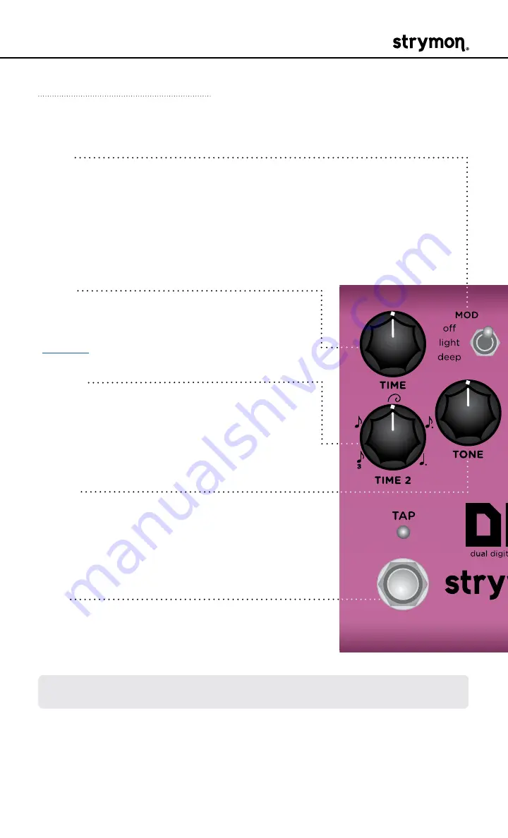
Knobs and Switches
Front Panel Controls
TIME
Controls the delay time for Delay 1� Acts as
a master time control for both delays� See
for details�
TIME 2
Sets the rhythmic subdivision relationship
between Delay 1 and Delay 2� Select from
triplet, eighth, golden ratio, dotted eighth, or
dotted quarter�
TONE
Sets the feedback filter response� Turn
counter-clockwise for high cut and clock-
wise for low cut� 12 o’clock provides a flat
response�
TAP
Tapping the footswitch sets the master delay
time� The
TAP
LED flashes
RED
to indicate
the tempo�
MOD
Sets the amount of modulation added to the delay lines:
off:
no modulation
light:
subtle modulation
deep:
thick, rich modulation
NOTE: Hold the
TAP
footswitch to engage circular repeats� Release the
footswitch to return to normal operation�