5
=
TECHNICAL PASSPORT, INSTALLATION AND MAINTENANCE INSTRUCTION
2
BOILER STRUCTURE
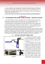
1. Air valve
2. Draft regulator
3. Support rod
4. Air heating chamber
5. Smoke outlet
6. Switch valve (only for U boilers)
7. Telescopic air supply pipe
8. Fuel loading opening
9. Air distributor
10. Fuel
11. Ash removal opening
12. Lifting cord with ring
13. Hook
14. Hot water pipe
15. Returning water pipe
16. Thermometer coupling
17. Pressure relief valve coupling 1,5 bar.
18. Bottom
19. Fire grate
20. Deflectors
21. Air injection collector
Figure 1
ATTENTION!
It is forbidden to change the construction of the boiler.
2.1
DESCRIPTION OF BOILER STRUCTURE
Boiler
– is a steel cylinder, enveloped in a larger diameter steel cylinder, which provides
thermal insulation. Heated water resides between these two cylinders. There is a draft
regulator on the front side of the boiler (2) (see 7.3). The construction has fuel loading (8),
ash removal (11 openings and a smoke outlet (5), as well as water supply (14 - 15),
thermometer (16) and pressure relief valve (17) openings. An air heating chamber is
installed in the upper part of the combustion chamber to improve the combustion quality and
heat transfer (4). The chamber holds a telescopic air supply pipe (7), at the end of which an
air distributor is attached (9).
“U’’ boiler, is designed to burn peat briquettes or coal, has a switch valve (6),
complemented with fire grate (19) and air injection collector (21).
“BIO’’ boiler, designed to burn firewood, pellets, sawdust briquettes or wood chips,
complemented with fire grate (19) and air injection collector (21).


