background image

Page 7 of 14 


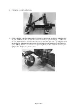
2.  Pull the lock pin out from the frame.  


3.  Before operation, open the release valve by turning the hand-wheel counter-clockwise. Expand 

the jack with the hand-wheel to place the rollers around the tire; position the jack so both rollers 
are in contact with the tire tread. To obtain the best control of the jack while expanding the rollers 
around the tire, place your left hand on top of the left side axle and place your right hand at the 
center of the pedal. Close the release valve by turning the hand-wheel clockwise to a snug and 
tight position. The jack may now be used.  


Summary of Contents for 61132

Page 1: ...Positioning Jacks Owner s Manual WARNING Read carefully and understand all ASSEMBLY AND OPERATION INSTRUCTIONS before operating Failure to follow the safety rules and other basic safety precautions may result in serious personal injury Item 61132 ...

Page 2: ...that you read the entire manual to become familiar with this product before you begin using it These jacks are designed for certain applications only Northern Tool and Equipment is not responsible for issues arising from modification or improper use of these products such as an application for which they are not designed We strongly recommend that these products not be modified and or used for any...

Page 3: ... Intended Use 4 Technical Specifications 4 Important Safety Information 4 Specific Operation Warnings 5 Operating Instructions 6 Maintenance 9 Troubleshooting 9 Parts Diagram 10 Parts List 11 Replacement Parts 12 Limited Warranty 13 ...

Page 4: ...thorized modification may impair the function and or safety and could affect the life of the product There are specific applications for which the product was designed Use the right tool for the job DO NOT attempt to force small equipment to do the work of larger industrial equipment There are certain applications for which this equipment was designed This product will be safer and do a better job...

Page 5: ...mask in dusty work conditions Also use non skid safety shoes hardhat gloves dust collection systems and hearing protection when appropriate This applies to all persons in the work area Do not overreach Keep proper footing and balance at all times CAUTION JACK SET USE AND CARE Do not force the jack set Products are safer and do a better job when used in the manner for which they are designed Plan y...

Page 6: ...y damage Operating Instructions WARNING Do not exceed the rated load capacity Use only on a hard level surface Do not start the vehicle s engine or drive with jacks in use Jacks are designed for hand maneuvering of vehicles only Do not use the jacks to lift tires wider than 12 inches Do not attempt to push the jacks over obstacles They are designed to be used on level and smooth surface only After...

Page 7: ...llers around the tire position the jack so both rollers are in contact with the tire tread To obtain the best control of the jack while expanding the rollers around the tire place your left hand on top of the left side axle and place your right hand at the center of the pedal Close the release valve by turning the hand wheel clockwise to a snug and tight position The jack may now be used ...

Page 8: ...t on the pedal depressing the pedal with smooth even strokes Cycle the pedal until the tire is lifted from the surface one inch or less After lifting the lower the tire is to the ground the more stable the jack will be After lifting be sure to always lock the pin in place before operation If using more than one jack repeat the process on the other tires and maneuver the vehicles as required 6 To r...

Page 9: ...intenance Point Daily before operating Use only a small amount of soap and a damp cloth to clean the jack set Troubleshooting Use the table below to troubleshoot problems before contacting service personnel or your local dealer If the problem continues after troubleshooting call your local dealer for assistance Failure Possible Cause Corrective Action The pedal will not move properly The pedal loc...

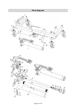
Page 10: ...Page 10 of 14 Parts Diagram ...

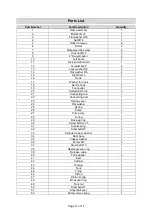
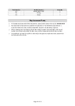
Page 11: ... 19 Foot pedal 1 20 Pedal pin Ø8x28 3 21 Connecting rod 1 22 Connecting bolt 1 23 Spring cover 1 24 Flat washer 1 25 Spring 1 26 Pump 1 27 Pump core 1 28 O ring 1 29 Back up ring 1 30 Screw M10x1 25 1 31 Small spring 1 32 Steel ball Ø6 3 33 Cylinder copper washer 1 34 Ram base 1 35 Copper washer 1 36 Screw M5 2 37 Steel ball Ø 5 1 38 Rectangle seal ring 1 39 Release valve 1 40 Tank washer 2 41 Ram...

Page 12: ... available for replacement The illustrations provided are a convenient reference to the location and position of parts in the assembly sequence When ordering parts the following information will be required item description item model number item serial number item lot date code and the replacement part reference number The distributor reserves the rights to make design changes and improvements to...

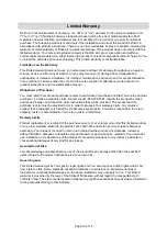
Page 13: ...y claim contact Us at 1 800 222 5381 identify the product by make and model number and follow the claim instructions that will be provided The product and the purchase receipt must be provided to Us in order to process Your warranty claim Any returned product that is replaced or refunded by Us becomes our property You will be responsible for return shipping costs or costs related to Your return vi...

Page 14: ...Page 14 of 14 Distributed by Northern Tool Equipment Company Inc Burnsville Minnesota 55306 www northerntool com Made in China ...

Reviews: