background image


18


10. 

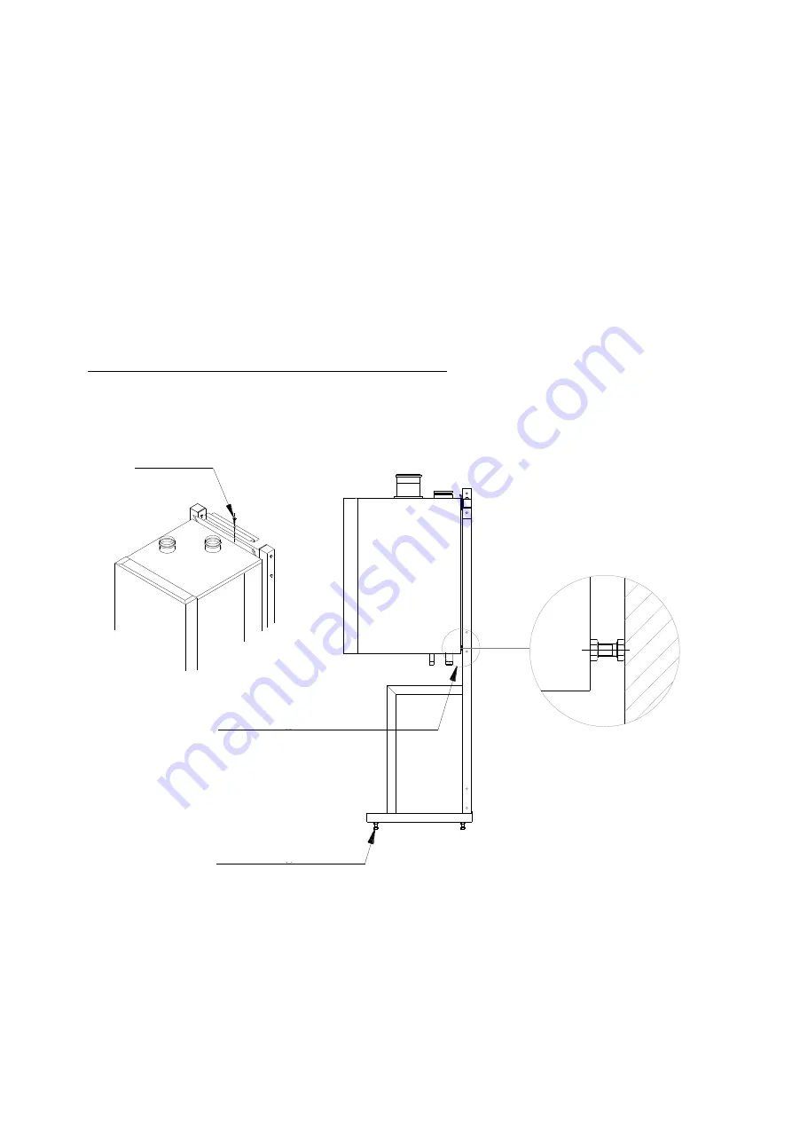
Mounting the Boilers on the Frame 

 
1.  Before  mounting  the  boiler  on  the  frame,  ensure  that  the  frame  is  level  both  horizontally  and  vertically.


If 

necessary, adjust with the adjusting bolts on the lower side of the frame (see Figure 10.1). 

 
2.  Hang the boilers on the frame.  


3.  Align the boilers with the L-stand in such a way that there is an exact 50 mm gap between the boilers. 
 
4.  Lock  the  suspension  bracket  with  the  locking  strip  to  prevent  the  boiler  from  falling  off  the  bracket  (see 

drawing). 

 
5.  Make sure that the boiler is at the right position (near level). 

The  boilers  must  hang  backwards  slightly  (1º  +/-  0.5º).  If  necessary,  adjust  with  the  adjusting  bolts  on  the 
lower rear side of the back panel (see Figure 10.1).  When the adjusting bolts are 

not

 sufficient, the space 

behind the bolts needs to be filled to achieve the correct position.  


Attention

The boiler must 

never


lean forward

 in the mounted position. 

 
6.  Next mount the hydraulic group and connecting sets. See chapter 11. 


Figure 10.1 Mounting details 


Levelling frame 

Locking 

Levelling boiler 

Summary of Contents for S-CBX 105

Page 1: ...ascade Kits Models 85 105 125 155 Installation Operating Manual 2 x 85 up to 6 x 155 Please read and understand before commencing installation and leave the manual with the customer for future reference 2019 05 01 v1 ...

Page 2: ......

Page 3: ...5 8 1 Frame elements 15 8 2 Procedure for mounting the frame 16 9 MOUNTING THE GAS HEADER 17 10 MOUNTING THE BOILERS ON THE FRAME 18 11 MOUNTING THE HYDRAULIC GROUP AND THE CONNECTING SETS 19 12 MOUNTING THE LOW LOSS HEADERS 20 13 DETERMINE MANAGING AND DEPENDING BOILERS 21 14 COMPLETE THE MECHANICAL INSTALLATION 21 15 MOUNT THE FLUE GAS AND AIR SUPPLY SYSTEMS 22 15 1 Individual flue systems 22 15...

Page 4: ... go into error the cascade configuration will continue to operate Strebel Ltd can supply standard cascade systems with mounting frame piping and low loss headers for up to six boilers depending on the range Larger amounts of boilers in a cascade combination are possible but require a dedicated system which must be designed separately The software allows for combining of up to 16 S CBX boilers in a...

Page 5: ... chapter 8 4 Mount the gas header This is described in detail in chapter 9 5 Mount the boilers on the frame This is described in detail in chapter 10 6 Mount the hydraulic group and the connecting sets This is described in detail in chapter 11 7 Mount the low loss header This is described in detail in chapter 12 8 Determine which boiler is managing and which are depending This is described in deta...

Page 6: ...to determine which combination of boilers can be applied to achieve the required power Total Power S CBX 85 S CBX 105 S CBX 125 S CBX 155 Total Number of Boilers 170 2 2 187 1 1 2 204 2 2 210 1 1 2 227 1 1 2 236 1 1 2 249 2 2 253 1 1 2 255 3 3 272 2 1 3 276 1 1 2 289 1 2 3 295 2 1 3 302 2 2 305 3 3 312 1 1 1 3 321 2 1 3 328 2 1 3 335 1 2 3 338 1 1 1 3 340 4 4 351 1 2 3 355 2 1 3 357 3 1 4 361 1 1 ...

Page 7: ...3 6 853 2 4 6 880 1 5 6 906 6 6 Figures in this column represent the nominal output in kW at 50 C 30 C Table 3 1 Cascade power calculation table based on S CBX boilers EXAMPLES 1 In case the required power is calculated at 275 kW the table will show you that the required cascade type and that the cascade configuration should have 2 boilers one S CBX 125 boiler and one S CBX 155 boiler 2 In case th...

Page 8: ...chapter is explained how to determine the dimensions of the cascade configuration and how much space is required in the room where the cascade configuration will be installed Figure 4 1 Dimensions front view L2 length incl low loss header L1 length frame EHS T0200 5050 ...

Page 9: ...s below EXAMPLES In case a cascade configuration for 275 kW is required which will exist of 2 boilers refer to Table 4 1 for the dimensions of the cascade configuration The table shows that frame length for this configuration is 1030 mm and the total length including the low loss header is 1428 mm In case a cascade configuration for 440 kW is required which will exist of 4 boilers refer to Table 4...

Page 10: ...loss header 487 487 H1 height gas 308 308 H2 height header coupling 257 257 H3 height couplings 380 380 D1 header connection size DN 80 PN6 3 DN 80 PN6 3 D2 header connection size DN 80 PN6 3 DN 80 PN6 3 D3 gas connection size R 2 R 2 A gas 253 253 B headers 466 466 Table 4 2 Dimensions S CBX cascade 360 up to 540 kW Number of Boilers 540 to 930 kW 4 Boilers 5 Boilers 6 Boilers L1 length frame 201...

Page 11: ... hydraulic and gas header groups Each connecting set contains one gas one supply and one return pipe More details can be found in chapter 6 5 Hydraulic and gas header group existing of 1 gas 1 supply and 1 return header including all mounting and connecting parts More details can be found in chapter 7 6 Low loss header to connect the hydraulic group to the heating installation Figure 5 1 Cascade p...

Page 12: ... Check valve Ball valve Coupling to return header Figure 6 1 Connecting sets The gas connecting set should be connected to the gas connection on the boiler The supply connecting set must be connected to the boiler supply connection front connection on the boiler and the return connecting set longest to the boiler return connection back connection on the boiler The open connection in the supply con...

Page 13: ...er red marking 3 Return header blue marking Figure 7 1 Parts hydraulic and gas header group 7 2 Support Beam and Support Brackets Figure 7 2 Headers support beam and support brackets 1 2 3 U bolt U bolt Support bracket water headers Support bracket gas header Headers support beam Seal plug ...

Page 14: ...the cascade configuration the headers come in the following size varieties Header Varieties Gas header DN50 DN80 Water header supply and return DN65 DN80 DN100 See also Table 4 1 Table 4 2 and Table 4 3 1 2 red blue 1 Gas connection set 2 Supply connection set 3 Return connection set E67 5020 002 3 3 3 ...

Page 15: ...e frame on which the boilers will be hung The basic frame exists of the following elements L shaped stands Top beam In between beam middle beam Mounting material bolts washers 1 Locking strip 2 In between beam 3 Top beam 4 L stand 5 Rectangular seal plug 70x50 6 Bolt M8x25 DIN933 7 Washer M8 DIN 125 1A B Figure 8 1 Frame elements ...

Page 16: ... the frame subsequently carry out the steps in the following procedure 1 Check after unpacking that all parts are actually present 2 Mount the in between beam s between the L stands Ensure that the beam s flange hole falls over the raised edge of the L stand connection hole Mount the beam s loosely do not yet tighten the bolts 3 Mount the top beam s between the L stands Ensure that the beam s flan...

Page 17: ...or some play tolerance for a neat installation After finishing the installation the support beam and brackets can be tightened 1 Mount the support beam s for the hydraulic and gas header group loosely between the legs of the L stands 2 Mount the support brackets for the gas header at nominal height See also Figure 7 2 3 Place the gas header s on the support brackets and fasten it them loosely with...

Page 18: ...king strip to prevent the boiler from falling off the bracket see drawing 5 Make sure that the boiler is at the right position near level The boilers must hang backwards slightly 1º 0 5º If necessary adjust with the adjusting bolts on the lower rear side of the back panel see Figure 10 1 When the adjusting bolts are not sufficient the space behind the bolts needs to be filled to achieve the correc...

Page 19: ...flat seal two part couplings 1 flat seal coupling for connection to boiler inside thread female thread 1 flat seal coupling for connection to connecting set outside thread male thread a Fit the flat seal couplings to the boiler and to the connecting set b Mount the pump to the boiler pay attention to its orientation c Mount the connecting set to the pump pay attention to its orientation d Bend the...

Page 20: ...40 to 930 kW E68 0300 503 200 x 200 x 5 Table 12 1 Low loss header connection sizes The low loss header can be fitted on the right hand side as well as on the left hand side without making any alterations to the supplied parts The gas connection can also be fitted on one of both sides independent from the side chosen for the low loss header 1 Mount the low loss header It can be mounted on the righ...

Page 21: ...eted with all other necessary parts and connections This may include All valves Non return valves Strainers Air separators Expansion vessel Overflow Attention The hydraulic piping of the Strebel Ltd cascade systems already contains non return valves underneath each boiler When other hydraulic systems are used non return valves must be fitted in the return pipe of each boiler The Installation Servi...

Page 22: ...tallation Service Manual of the S CBX boiler series Flue gas and air supply system For each boiler the combined resistance of the individual flue gas and air inlet pipe can be calculated and checked with the maximum resistance allowed For resistance tables and example calculations we refer to the mentioned chapter in the boiler manual 15 2 Common flue system A common flue system must be designed i...

Page 23: ...arameters required for the cascade configuration is described in detail in the chapter s about Cascading in the Installation Service Manual of the S CBX boiler series Attention Changes in parameters may only be carried out by a skilled installation service engineer who has had specific training for setting up the S CBX boilers He will be able to check whether the installation functions correctly a...

Page 24: ...ts and groups 11 Figure 6 1 Connecting sets 12 Figure 7 1 Parts hydraulic and gas header group 13 Figure 7 2 Headers support beam and support brackets 13 Figure 7 3 Headers and connecting sets 14 Figure 8 1 Frame elements 15 Figure 10 1 Mounting details 18 Figure 12 1 Low loss header 20 Figure 16 1 Boiler display 23 19 2 List of tables Table 3 1 Cascade power calculation table based on CB boilers ...

Page 25: ...25 20 Appendix A Cascade Parts The following drawings give an overview of parts used in a cascade configuration Top view Front view 5 E67 5020 002 ...

Page 26: ...0 11 Low Loss Header DN65 DN80 DN100 12 Gas Connecting Set 13 Gas Connecting Set 1 14 Supply Connecting Set R1 15 Return Connecting Set R1 16 Supply Connecting Set R1 Return Connecting Set R1 Alternative to 15 not in figure 18 Reducing Ring 19 Seal Cap Rp2 DN50 DN80 to block gas header 20 Drain Tap G 21 Blind Flange DN65 DN80 DN100 to block water headers 22 Air Vent 23 External Temperature Sensor ...

Page 27: ......

Page 28: ...Road Farnborough Hampshire GU14 7QU T 01276 685422 F 01276 685405 E info strebel co uk I www strebel co uk Further information on our complete product range is available from our website CAST IRON CONDENSING STEEL SHELL WATER HEATERS RENEWABLES FLUES ACCESSORIES ...

Reviews: