Page 7
23/03/01
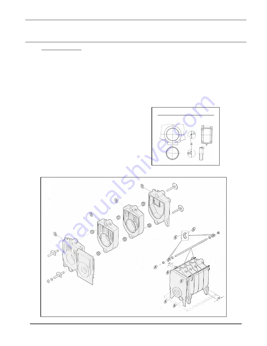
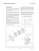
Once assembled, the boiler block is to be secured with
the tie bars (2 at the top, and 2 at the bottom). Prior to
screwing nuts up ensure the two disc springs (5)&(6)
are slotted on with concave sides facing each other.
The nuts can now be tightened until the disc springs
flatten.
The burner door hinges should now be fitted on the
left or right hand side of the front section depending
on requirements. Ensure the eyelet screws (door
hinge) are at the same depth and when the door is
closed it should press flat with the front section.
Boiler Block Assembly
The boiler block is assembled by ‘pulling-up’ each
section in turn starting from the rear section (1). All
other sections (2)(3)(4) are mounted individually
using the pulling-up tools.
One face of the adjoining sections must have a length
of mastic sealing strand placed into the mastic groove.
Each of the boiler nipples must be inspected to ensure
there is no damage apparent. The nipples and nipple
ports should then be kept free from dirt and checked
at each stage of assembly. Particles of dirt which are
not removed lead to leakage.
The accompanying nipple jointing oil serves as a
lubricant as well as a waterproof seal and must be
used.
Boiler nipples and nipple ports must align exactly at
all stages of assembly. An inclined, retracted nipple
leads to leakage.
The clearance between the sections throughout the
pulling-up stages should always be even. If the
clearance is uneven, a flat chisel should be inserted
into the narrower point and the sections pulled up
until the clearance is even again.
Diagram showing nipple & boring
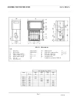
ASSEMBLY INSTRUCTIONS FOR: Ca 7s / BCa 7s


