background image

Page 4 

23/03/01 

ASSEMBLY INSTRUCTIONS FOR:                                                                               Ca 7s / BCa 7s


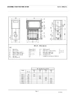
Boiler Dimensions 

Ca 7s  - Dimensions  

Boiler   LK mm  Tmm 


Ca7s-4  865 

555 

Ca7s-5  1015 

705 

Ca7s-6  1165 

855 

Ca7s-7  1315  1005 
Ca7s-8  1465  1155 
Ca7s-9  1615  1305 

Ca7s-10  1765  1455 

KEY: 
1.1       Boiler Flow               130mm NW65 
2.1       Boiler Return            130mm NW65 
35.1     Boiler Drain              3/4” 

Summary of Contents for BCa7s

Page 1: ...Page 1 23 03 01 Ca 7s and BCa 7s 61 235 kW INSTALLATION AND OPERATING INSTRUCTIONS ...

Page 2: ...y connections Ca7s Jacket assembly Calorifier assembly BCa7s Jacket assembly Continued Electrical connection and Instrument control panel Continued Control module options Control module diagrams Installation of electronic control modules Terminal wiring diagram Schematic wiring diagram Important notes burner connection information PAGE 3 4 5 6 7 8 9 10 11 12 13 14 15 16 17 18 19 20 21 ...

Page 3: ...h efficiency Built in instrument panel with multiple control possibilities and retro fit control options Easy erection and cleaning Modern design Operating conditions Boiler Maximum operating temperature up to 110ºC Maximum operating temperature up to 120ºC depending on technical safety of the equipment Maximum operating pressure 4 0 bar Maximum test pressure 5 2 bar Min thickness 60mm A B Ca 7s 4...

Page 4: ... 7s Boiler Dimensions Ca 7s Dimensions Boiler LK mm Tmm Ca7s 4 865 555 Ca7s 5 1015 705 Ca7s 6 1165 855 Ca7s 7 1315 1005 Ca7s 8 1465 1155 Ca7s 9 1615 1305 Ca7s 10 1765 1455 KEY 1 1 Boiler Flow 130mm NW65 2 1 Boiler Return 130mm NW65 35 1 Boiler Drain 3 4 ...

Page 5: ...75 1625 2075 Ca7s 8 1465 1625 2075 Ca7s 9 1615 2075 Ca7s 10 1765 2075 1 1 Boiler flow 130mm NW65 2 1 Boiler return 130mm NW65 10 Primary pump 1x230V 1 33 Primary connection pipe 1 1 34 Return connection pipe 1 1 35 Air vent 3 8 35 1 Boiler drain off 35 2 HWS drain off 38 HWS water connection flow 1 2 39 Cold water connection 1 2 40 Circulation connection 44 1 Non return valve Available for calorif...

Page 6: ...earances required in boiler room The clearance details shown above are required for access to the boilers for maintenance purposes Slight variations may apply depending on the specific installation ASSEMBLY INSTRUCTIONS FOR Ca 7s BCa 7s ...

Page 7: ... using the pulling up tools One face of the adjoining sections must have a length of mastic sealing strand placed into the mastic groove Each of the boiler nipples must be inspected to ensure there is no damage apparent The nipples and nipple ports should then be kept free from dirt and checked at each stage of assembly Particles of dirt which are not removed lead to leakage The accompanying nippl...

Page 8: ...rts and take up slack Pulling up flange 1st Intermediate section Pulling up Brass Brass Rear Spanner Flange Tighten flanges alternately until faces are touching Blanking Flange Blanking Flange Tie bar M12 Tie bar M20 Cast lug for tie bar Once the boiler block is pulled up use the tie bars to secure as shown ASSEMBLY INSTRUCTIONS FOR Ca 7s BCa 7s ...

Page 9: ...a the filling and draining cock Separate by driving flat wedges around the perimeter of the join between sections New nipples MUST be used for re assembly Assemble and repeat test The order of assembly from 1 to 7 must be observed Important points When fitting the long injection tube 1 only fitted to boilers with 7 sections or more care should be taken to ensure that the holes for the direction of...

Page 10: ...te The sensor leads capillary tubes should not be kinked The jacket assembly should be in the following order 1 Insulation under the boiler both left and right 2 Boiler side jackets left and right 3 Rear bottom bracing angle 4 Front bracing bracket 5 Rear inner insulation 6 Position burner cable according to door hinging 7 Position instrument control panel 8 Mount control panel to mounting bracket...

Page 11: ...n connection to calorifier 3 Header for the flow connection to the calorifier 4 Calorifier mounting bracket 5 Calorifier 6 Pipework to calorifier flow 7 Pipework to calorifier return 8 Blank flange for return connection 9 Blank flange for flow connection 10 Reflector plate 11 Injector tube Boiler block showing calorifier ASSEMBLY INSTRUCTIONS FOR Ca 7s BCa 7s ...

Page 12: ...Page 12 23 03 01 ASSEMBLY INSTRUCTIONS FOR Ca 7s BCa 7s BCa7s Jacket assembly Follow the steps below for completion of the jacket assembly ...

Page 13: ...e calorifier control thermostat sensor 5 must be pushed into the lower sensor pocket with the retaining spring The calorifier thermometer 6 must be pushed into the upper sensor pocket All sensor leads capillary leads must not be kinked Note Mains connection should be made via the rear of the boiler through to the control panel It must not be connected directly to the front of the boiler via the ca...

Page 14: ...the stage 1 burner operation H Hours Run Meter blanked as standard Burner Stage 2 Shows running time of the stage 2 burner operation I Frequency of Switching Meter for Stage 1 blanked as standard J Frequency of Switching Meter for Stage 2 blanked as standard K Summer Winter Switch For switching boiler between modes to supply HWS only in the summer period L Calorifier Control Thermostat Set for the...

Page 15: ... Panel The diagrams opposite shows connections to the instrument control panel Key 1 Burner Cables 2 Power Supply Connection 3 Stage 1 Stage 2 Thermostat Sensor boiler Thermometer Sensor Pockets 4 Calorifier Thermostat Sensor Pocket 5 Calorifier Thermometer Sensor Pocket ...

Page 16: ...t DIN 4791 Weiland Connector 7 way for stage 1 burner operation DIN 4791 Additional Weiland Connector 4 way for use with Hi Low Burners A Power Supply 230V 50Hz B Burner Connections Plug and Socket Looms K Boiler Circulating Pump Interlock W Flue Gas Damper Interlock X Safety Solenoid Valve Interlock Y Calorifier Thermostat Interlock Z Provision for Remote High Temperature Limit Indication D1 Calo...

Page 17: ...it Indication 30 Calorifier Control Thermostat DIN 4791 Weiland Connector 7 way for stage 1 burner operation DIN 4791 Additional Weiland Connector 4 way for use with Hi Low Burners A Power Supply 230V 50Hz B Burner Connections Plug and Socket Looms C Calorifier Primary Circulating Pump K Boiler Circulating Pump Interlock W Flue Gas Damper Interlock X Safety Solenoid Valve Interlock Y Calorifier Th...

Page 18: ...ler Thermostat Stage 1 1 6 Boiler Thermostat Stage 2 1 8 Hours Run Meter Stage 1 1 8a Frequency of Switching Stage 1 optional 1 9 Hours Run Meter Stage 2 1 9a Frequency of Switching Stage 2 optional 1 14 Boiler Limit Thermostat for operation at 110ºC optional extra 1 20 Burner Lock out Lamp 1 21 High Limit Lamp 1 23 Fuse 6 3A K2B Instrument Control Panel Internal Wiring Diagram ...

Page 19: ...h Limit Lamp 1 23 Fuse 6 3A Legend 1 1 Power Switch ON OFF 1 2 Summer Winter Switch 1 3 High Limit STB Test Switch 1 4 Boiler Limit Thermostat 1 5 Boiler Thermostat Stage 1 1 6 Boiler Thermostat Stage 2 1 7 Calorifier Thermostat 1 8 Hours Run Meter Stage 1 1 8a Frequency of Switching Stage 1 optional 1 9 Hours Run Meter Stage 2 1 9a Frequency of Switching Stage 2 optional 1 14 Boiler Limit Thermos...

Page 20: ...as temperature is too low the baffles from the 3rd flue pass can be taken out If necessary the 2nd flue pass baffles can also be removed NB Every change made to the flue baffles requires re commissioning of the burner settings Electrical connections must be carried out by qualified personnel in accordance with instructions supplied Electrical leads and oil pipes should never be fastened to the boi...

Page 21: ......

Page 22: ...mley Road Camberley Surrey GU16 7PB Telephone 01276 685422 Fax 01276 685405 E mail address info strebel co uk Website www strebel co uk THE COMPANY RESERVES THE RIGHT TO CHANGE SPECIFICATIONS AND DIMENSIONS WITHOUT NOTICE ASSEMBLY INSTRUCTIONS FOR Ca 7s BCa 7s E O E ...

Reviews: