background image

Inspecting the Cabinet and System

Unpacking and Positioning the Cabinet

1-17

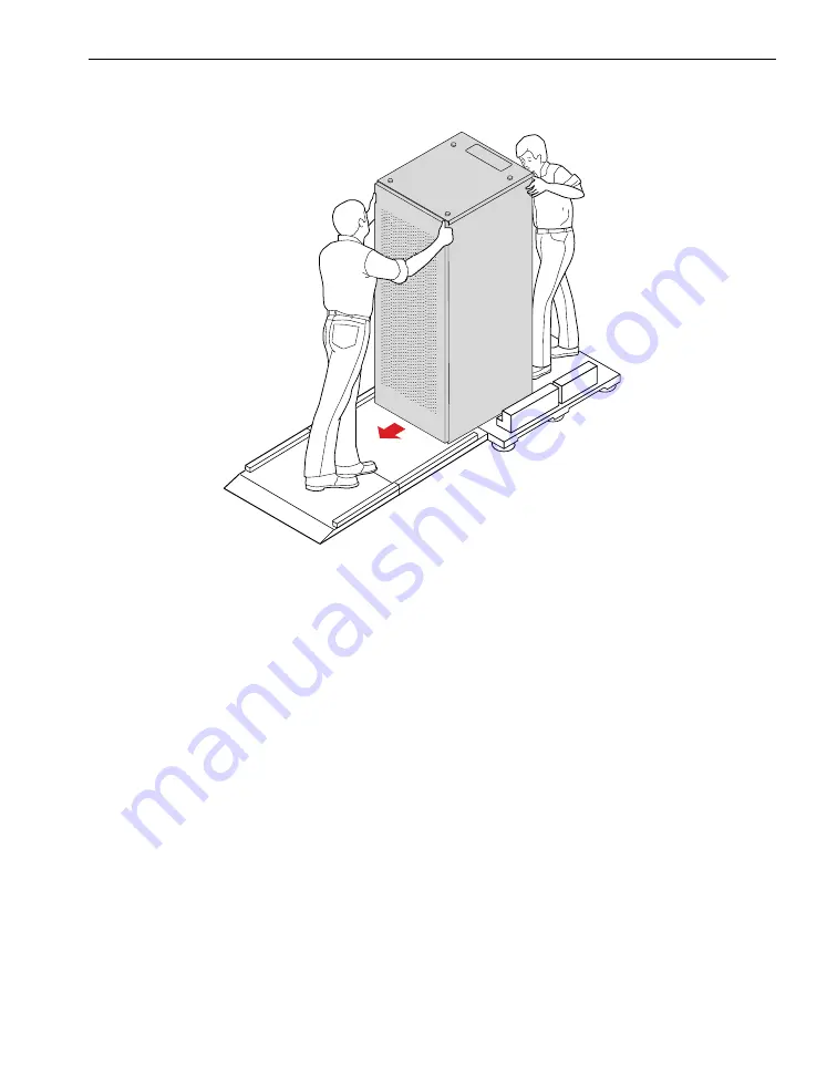
Figure 1-14. Moving Cabinet Down Pallet Ramp

2. Check the cabinet and systems for damage, as the next section describes.

Inspecting the Cabinet and System

Check all equipment and components for damage by performing the following 
procedure.

1. Open the rear door of the cabinet. From the bottom of the cabinet, remove and 

discard the desiccant bags.

2. Check the cabinet and system for damage. Verify that the cabinets and panels 

have no dents, scratches, or scrapes.

If you noticed damage, contact the CAC.

Verifying the Stratus Serial Number

Find the equipment label to check the Stratus serial number. To find the equipment 
label, open the rear door of the cabinet. The equipment label is affixed to the upper-left 
side of the cabinet. 

Figure 1-15

 shows the equipment label.

upk011a

Summary of Contents for ftServer V 2404

Page 1: ...Stratus Technologies R004S 02 Stratus ftServer V 2404 V 4408 V 6408 and V 6512 Hardware Installation Guide ...

Page 2: ...se by Stratus personnel and are subject to change without warning This document is protected by copyright All rights are reserved Stratus Technologies grants you limited permission to download and print a reasonable number of copies of this document or any portions thereof without change for your internal use only provided you retain all copyright notices and other restrictive legends and or notic...

Page 3: ...als 1 19 2 Connecting and Powering On the System 2 1 Connecting External Components to the System 2 1 Connecting the RSN Console Server 2 1 Connecting the AA E97900 RSN Console Server to the Internet 2 3 Connecting the AA E97900 RSN Console Server to a Modem 2 7 Connecting the AA E97700 RSN Internet Console Server to the Internet 2 10 Connecting the AA E96600 RSN Dialup Console Server to a Modem 2...

Page 4: ...g On the ftServer System 2 38 Related Documentation 2 38 Appendix A Removing and Replacing Components A 1 Removing and Replacing a U581V Fabric Switch A 1 Removing a U581V Fabric Switch A 1 Replacing a U581V Fabric Switch A 8 Removing and Replacing the Power Supply Fan A 17 Removing the Power Supply Fan Assembly A 18 Replacing the Power Supply Fan Assembly A 19 ...

Page 5: ...e AA E97900 Power Cord and Cables in an Internet Connection 2 5 Figure 2 4 AA E97900 RSN Console Server Connections to a Modem 2 7 Figure 2 5 Connecting the AA E97900 RSN Console Server Cables and Power 2 9 Figure 2 6 AA E97700 RSN Internet Console Server Connections 2 11 Figure 2 7 Connecting AA E97700 Power Cord 2 12 Figure 2 8 Connecting RSN Dialup Console Server to Modem 2 13 Figure 2 9 Connec...

Page 6: ...Tape Drive 2 37 Figure 2 33 Powering On System 2 38 Figure A 1 Removing Bezel from Fabric Switch A 2 Figure A 2 Removing Air Flow Bracket A 3 Figure A 3 Disconnecting Cables at Front of Fabric Switch A 4 Figure A 4 Removing Power Cord at Rear of Fabric Switch A 5 Figure A 5 Pushing Fabric Switch Toward Front of Cabinet A 6 Figure A 6 Sliding Fabric Switch Out of Cabinet A 7 Figure A 7 Removing Sho...

Page 7: ...Tables vii Tables Table 1 1 Stabilization Guidelines 1 18 Table 2 1 RSN Console Server Connections 2 2 ...

Page 8: ...Tables viii Stratus ftServer V 2404 V 4408 V 6408 and V 6512 Hardware Installation Guide R004S ...

Page 9: ...mation This manual is a revision It adds information about installing the AA E97900 RSN console server to the Internet or to a modem Notation Conventions This document uses the notation conventions described in this section Warnings Cautions and Notes Warnings cautions and notes provide special information and have the following meanings W A R N I N G A warning indicates a situation where failure ...

Page 10: ...ystem doc Monospace italic represents terms that are to be replaced by literal values In the following example the user must replace the monospace italic term with a literal value list_users module module_name Monospace bold represents user input in examples and figures that contain both user input and system output which appears in monospace For example display_access_list system_default dev m1 s...

Page 11: ...system is covered by a service agreement please contact the Stratus Customer Assistance Center CAC or your authorized Stratus service representative For information about how to contact the CAC see the following Web site http www stratus com go support ftserver location Commenting on the Documentation To provide corrections and suggestions on the documentation send your comments in one of the foll...

Page 12: ...lowed by form then press Enter or Return Enter this document s part number R004S then enter the name of your comments file in the comments_path field Press the key that performs the CYCLE function to change the value of use_form to no and then press Enter N O T E If comment_on_manual does not accept the part number of this document which may occur if the document is not yet registered in the manua...

Page 13: ... on page 1 17 Stabilizing the System on page 1 18 Disposing of Shipping Materials on page 1 19 Safety Considerations To ensure a safe and effective installation follow the procedures exactly as they are written in this manual Before installing the system take the following important precautions Do not attempt to install the system without the assistance of another able bodied person The size and w...

Page 14: ...conductive objects such as rings bracelets and keys Safety Notices W A R N I N G Risk of explosion if battery is replaced by an incorrect type Dispose of used batteries according to the instructions provided with the battery W A R N I N G If you receive locking power cords with your system do not substitute other power cords Use of the locking power cords ensures proper grounding of the system W A...

Page 15: ...x wrenches ESD static kit Assorted tie wraps Unpacking the Cabinet The cabinet mounted system is enclosed in a cardboard shipping container which is secured to a shipping pallet by exterior tie down straps Inside the cardboard interior straps secure the cabinet to the pallet A ramp for rolling the cabinet off the pallet is attached to the front of the shipping container along with two transition p...

Page 16: ...ted C A U T I O N If you received the wrong shipment or if a handling indicator has been activated do not proceed with the unpacking Contact the CAC immediately 3 Verify that the area through which you must move the system has adequate clearance as the following figures indicate Figure 1 2 shows the dimensions of a packaged 38U cabinet Figure 1 3 shows the clearances required at the installation s...

Page 17: ...2 Dimensions of Packaged 38U Cabinet Figure 1 3 Clearances Required at Installation Site upk002a 80 in 2m 41 in 104 14 cm 53 in 134 62 cm 5 in 12 7 cm 38U Cabinet msys046 Cabinet on Pallet Pallet Ramp Unload From This End 42 in 107 cm 42 in 107 cm 150 in 381 cm 42 in 107 cm ...

Page 18: ...Cabinet to the Installation Site W A R N I N G To avoid personal injury or damage to the system two persons are required to move unpack and install an ftServer system Because of the size and weight of ftServer systems have professional movers deliver and move the packaged units to the installation site C A U T I O N To prevent or minimize condensation on the system s internal and external surfaces...

Page 19: ...s are required to perform the following procedures 1 Orient the system package so that the package and the ramp have as a minimum the clearance shown in Figure 1 3 Also verify that you have enough clearance above the system to remove the top cardboard cap 2 With one person holding the ramp in place use the metal shears to cut the exterior shipping straps To avoid injury while cutting each strap ho...

Page 20: ... ramp are two accessory boxes which contain various components and documentation Remove the boxes and set them aside for later use N O T E It is possible that the system will include only one accessory box 4 Remove the cardboard pieces of packing material surrounding the cabinet see Figure 1 5 These pieces include two C fold sleeves around the sides of the cabinet and two caps at the top upk003a ...

Page 21: ...he cabinet C A U T I O N If condensation exists inside the plastic wrap you must provide a stabilization period for the system Stabilizing the System on page 1 18 provides complete information about the stabilization process 6 Use the strap buckles to loosen the interior shipping straps that secure the cabinet to the pallet See Figure 1 6 upk004 ...

Page 22: ...t the top front and top rear of the cabinet 8 Loosen but do not remove the bolts that secure the wooden restraint blocks to the pallet at the bottom sides of the cabinet See Figure 1 7 Note that there are no bolts on the wooden restraint blocks at the bottom rear of the cabinet To loosen the bolts use the 9 16 inch socket wrench You may need to hold the nut underneath the pallet that secures the b...

Page 23: ...estraint Blocks 9 Loosen and remove the bolts that secure the wooden restraint block at the front door of the cabinet Then remove the block 10 Remove the lever bar from its storage location see Figure 1 1 and insert it in the center slot of one of the sides as shown in Figure 1 8 upk006a Bolts ...

Page 24: ...sons Serious personal injury and damage to or destruction of the system is possible if the procedure is attempted by only one person 11 Standing near the lever bar and with your assistant on the opposite side of the cabinet as shown in Figure 1 9 push down on the lever with your foot and carefully guide the cabinet with your arms tilting it toward the other person who supports the cabinet upk007b ...

Page 25: ...ioning the Cabinet 1 13 Figure 1 9 Tilting Cabinet 12 While the system is tilted reach down and slide the wooden restraint blocks to the side and out from under the system See Figure 1 10 Figure 1 10 Sliding Back Wooden Restraint Blocks upk008a msys102 ...

Page 26: ...together The ramp is secured to the front of the cabinet on the pallet To assemble the pallet ramp and secure it to the pallet perform the following procedure 1 With the pallet ramp separated from the pallet performed in step 3 in the previous procedure remove the bolt see Figure 1 11 at the upper edge of the ramp and separate the lower end of the pallet ramp Figure 1 11 Removing Bolt 2 Fit the be...

Page 27: ...ing Up the Pallet Ramp Unpacking and Positioning the Cabinet 1 15 Figure 1 12 Assembling and Positioning Ramp 3 Position the pallet ramp under the pallet at the front of the cabinet see Figure 1 12 upk010a ...

Page 28: ...the cabinet Figure 1 13 Attaching Transition Plates Removing the Cabinet from the Pallet W A R N I N G Two persons are required to remove the cabinet from the pallet 1 With the help of another person slowly and carefully roll the cabinet down the ramp with one person at the front and one at the back See Figure 1 14 Each person must hold the upper portion of the cabinet with both hands W A R N I N ...

Page 29: ...the rear door of the cabinet From the bottom of the cabinet remove and discard the desiccant bags 2 Check the cabinet and system for damage Verify that the cabinets and panels have no dents scratches or scrapes If you noticed damage contact the CAC Verifying the Stratus Serial Number Find the equipment label to check the Stratus serial number To find the equipment label open the rear door of the c...

Page 30: ...t develop condensation Therefore before you install and power on the system you must inspect it for condensation and if necessary stabilize it To stabilize a system let it stand unpacked and without its plastic wrap in the open air of an office environment 1 Inspect the system for condensation Use the guidelines in Table 1 1 to determine if the system requires a stabilization period before you ins...

Page 31: ...riods until there are no signs of condensation C A U T I O N Before you power on the system verify that the installation site environment meets the environmental operation and power requirements specified in the Stratus ftServer V 6512 System Site Planning Guide R675 and Stratus ftServer V 2404 V 4408 and V 6408 Systems Site Planning Guide R645 Disposing of Shipping Materials The shipping material...

Page 32: ...Disposing of Shipping Materials 1 20 Stratus ftServer V 2404 V 4408 V 6408 and V 6512 Hardware Installation Guide R004S ...

Page 33: ...ures on page 2 22 Connecting the RSN Console Server Connecting a system to the Stratus RSN allows the CAC to remotely diagnose troubleshoot and resolve problems online To connect to the RSN ftServer systems use a modem or an Internet connection For information on processes files and commands required for RSN support see OpenVOS System Administration Administering and Customizing a System R281 When...

Page 34: ...1 summarizes how the RSN console servers connect to the RSN C A U T I O N You must install the RSN console server and modem if present on a flat surface such as a table or rack space Do not place these components on top of a system cabinet Table 2 1 RSN Console Server Connections RSN Console Server Connects to Internet Connects to Modem Dialup AA E97900 Yes Yes AA C72100 modem AA E97700 Yes No AA ...

Page 35: ...ure 2 1 shows the AA E97900 RSN console server connections to the Internet Figure 2 1 AA E97900 RSN Console Server Connections to the Internet 1 COM 1 port 5 Ethernet cable 2 RJ 45 to DB 9 serial cable 6 Ethernet port LAN2 3 Ethernet switch port 21 7 Ethernet port LAN1 4 AA E97900 RSN console server 3 5 4 6 7 2 1 Network connection to Internet vos239 ...

Page 36: ...st strap to perform this procedure 1 Connect the RS 232 cable RJ 45 number 2 in Figure 2 2 to serial port 1 on the console server number 1 in Figure 2 2 and to the COM 1 port top port on the server s backplane number 1 in Figure 2 1 N O T E This is not a required connection The CAC uses it as a manual connection from the PC console if a Telnet connection is not available Figure 2 2 AA E97900 RSN C...

Page 37: ...nternet Connection 3 Connect the Ethernet cable number 3 from the Ethernet switch to the LAN2 port the upper port of the console server 4 Connect the Ethernet cable number 4 from the external network to the LAN1 port the lower port of the console server 5 Turn the console server power switch to the on 1 position 1 Power switch 4 Ethernet cable from port LAN1 to Internet 2 Power cord 5 RJ 45 to DB ...

Page 38: ...est the operation of the console server by sending an RSN mail message to the Stratus Customer Assistance Center CAC or your authorized Stratus service representative and asking them to connect to your server If the console server is not working the CAC or your authorized Stratus service representative will help you correct the problem ...

Page 39: ... 4 shows the AA E97900 RSN console server connections to a modem Figure 2 4 AA E97900 RSN Console Server Connections to a Modem 1 COM 1 port 6 Ethernet port LAN2 2 RJ 45 to DB 9 serial cable 7 RJ 45 to DB 25 serial cable 3 Ethernet switch port 21 8 AA C72100 modem 4 AA E97900 RSN console server 9 Phone line 5 Ethernet cable 3 5 4 6 2 1 vos239a 7 8 9 ...

Page 40: ...or later 2 Wear an ESD wrist strap to perform this procedure 1 Connect the RS 232 cable number 4 in Figure 2 5 to serial port 1 on the console server and to the COM 1 port top port on the server s backplane number 1 in Figure 2 4 N O T E This is not a required connection The CAC uses it as a manual connection from the PC console if a Telnet connection is not available 2 With the console server pow...

Page 41: ...console server 4 Connect the other end of the serial cable number 7 in Figure 2 4 to the AA C72100 modem number 8 in Figure 2 4 5 Connect a telephone line number 9 in Figure 2 4 from the modem to a wall jack 6 Connect the Ethernet cable number 3 in Figure 2 5 to port LAN2 the upper port on the console server 1 Power switch 4 Serial cable to port 1 2 Power cord 5 Serial cable to port 2 3 Ethernet c...

Page 42: ... correct the problem Connecting the AA E97700 RSN Internet Console Server to the Internet Perform the following procedure to install the AA E97700 RSN Internet console server N O T E S 1 The AA E97700 RSN Internet console server requires OpenVOS Release 17 1 0 or later 2 Wear an ESD wrist strap to perform this procedure 1 Connect the RS 232 cable RJ 45 from serial port 1 on the RSN Internet consol...

Page 43: ...nections 2 Connect a Category 5 Ethernet cable from the external network to the RSN console server s LAN1 Ethernet port number 7 in Figure 2 6 1 COM 1 port 5 RSN Internet console server 2 Serial line 6 Ethernet port LAN2 3 U772 Ethernet switch port 21 7 Ethernet port LAN1 4 Ethernet cable 3 4 5 6 7 2 1 Network connection to Internet vos236f ...

Page 44: ...sole server s LAN2 Ethernet port numbers 3 4 and 6 in Figure 2 6 N O T E If a longer Ethernet cable is required customers must supply it 4 With the RSN console server power switch in the off 0 position plug the power cord into the console server 100 240 VAC VDC connector and into the AC wall outlet Figure 2 7 Figure 2 7 Connecting AA E97700 Power Cord 5 Turn the RSN console server power switch to ...

Page 45: ...alup console server the customer site requires one analog telephone line for a connection to the modem as well as a telephone line to use when calling for service 1 Connect the DB 25 RS 232 cable marketing ID B10102 10 from serial port 1 on the RSN console server to the DTE connector on the modem see callouts 2 and 4 in Figure 2 8 Tighten the connector screws Figure 2 8 Connecting RSN Dialup Conso...

Page 46: ...Console Server s Ethernet Cable and Power Cord 3 Connect the RSN console server s power cord to the console server 7 24 VDC connector number 3 in Figure 2 9 to the AC wall outlet number 4 in the figure 4 Connect a DB 9 RS 232 null modem cable marketing ID B10106 25 number 1 in Figure 2 10 from serial port 2 of the RSN console server number 2 in the figure to the COM 1 port top port on the rear of ...

Page 47: ... PC console if a Telnet connection is not available Figure 2 10 Connecting RSN Dialup Console Server to COM 1 Port 5 Connect one end of the customer supplied telephone line to the modem connector labeled PHONE on the modem and connect the other end to the telephone wall jack Figure 2 11 1 DB 9 RS 232 cable from RSN console server serial port 2 2 RSN console server vos228a 1 2 ...

Page 48: ... and to the AC wall outlet Figure 2 11 Connecting the ftScalable Storage System Stratus provides the following RAID storage system products The original ftScalable Storage system This manual refers to this system as first generation ftScalable Storage The second generation of ftScalable Storage This manual refers to this system as ftScalable Storage G2 1 Telephone line to wall jack 3 Power cord 2 ...

Page 49: ...y This is not meant to be a permanent connection Connecting the PC Console The customer must supply a PC known as the system console or PC console It must have the following One of the following newly installed operating systems Microsoft Windows 7 Windows XP or Windows Vista A serial port or USB to serial port converter TinyTERM terminal emulation software installed Stratus provides this terminal...

Page 50: ...re Installation Guide R004S Figure 2 12 Connecting PC Console to COM 2 Port 2 Connect a customer provided Category 5 Ethernet cable from the Ethernet port on the PC console to port 21 of U772 Ethernet Switch B numbers 1 and 2 in Figure 2 13 1 DB 9 cable from COM 2 port 2 Serial port on PC console vos2 1 2 ...

Page 51: ... to the System Connecting and Powering On the System 2 19 Figure 2 13 Connecting PC Console to U772 Ethernet Switch B 1 Port 21 of U772 Ethernet Switch B 3 Customer supplied Ethernet cable 2 Ethernet port on PC console vos063c 1 2 3 ...

Page 52: ... is properly assembled by following the assembly and physical installation instructions described in the UPS vendor s documentation 2 Connect the AC power cords to the UPS unit For UPS models not qualified by Stratus you must work with the UPS vendor and Stratus to properly size and configure the UPS for the ftServer module 3 Use two customer provided Category 5 Ethernet cables to connect the UPS ...

Page 53: ... 21 Figure 2 14 Connecting UPS Units to U772 Ethernet Switches 1 A side UPS 4 Port 23 of U772 Ethernet Switch A 2 B side UPS 5 Port 23 of U772 Ethernet Switch B 3 Customer supplied Ethernet cable vos063d 13 14 15 16 17 18 19 20 21 22 23 24 13 14 15 16 17 18 19 20 21 22 23 24 1 2 3 4 5 ...

Page 54: ...ht side rail screws and two cabinet screws front with washers to perform the installation 1 Attach the two side rails to the tape drive enclosure by aligning the screw holes in the side rails see Figure 2 15 with the holes in the side of the drive Place the rails as shown in the figure Attach four screws to each rail Figure 2 15 Attaching the Rails to the 1U Tape Drive Enclosure 2 Align the rails ...

Page 55: ...Connecting External Components to the System Connecting and Powering On the System 2 23 Figure 2 16 Inserting the Enclosure into the Cabinet vos244 ...

Page 56: ...r 3 in the figure and the FC cable number 4 in the figure 5 Connect the Ethernet cable to the maintenance switch 6 Press the safety tabs to unlock the enclosure and then push it all the way into the cabinet 7 Attach the two screws and washers number 1 in the figure to the front of the enclosure 8 Move the power switch to the 1 on position to power on the drive Logically install each tape drive in ...

Page 57: ...ve Enclosure Perform the following tasks to install the optional 2 U tape drive enclosure in your ftServer module You will need a 2 Phillips screwdriver a large flathead screwdriver and a cage nut tool to perform the installation 1 At the front and rear of the cabinet install cage nuts in the following locations see Figure 2 18 First U bottom hole First U top hole Figure 2 18 Installing Cage Nuts ...

Page 58: ...2 Hardware Installation Guide R004S 2 Loosen the two screws at the rear of the rail to allow the adjustable section to slide Figure 2 19 Figure 2 19 Loosening Screws on Rail 3 Secure the rails using two screws in the front and two in the rear Figure 2 20 Figure 2 20 Securing Rails 1 Screws 1 Screws ...

Page 59: ...nents to the System Connecting and Powering On the System 2 27 4 Tighten the two screws that hold the adjustable section Figure 2 21 Repeat for the other side Figure 2 21 Tightening Screws that Hold Adjustable Section 1 Screws ...

Page 60: ...8 and V 6512 Hardware Installation Guide R004S 5 Pull the innermost section of the rail out until it stops Then pull the green release button and pull the inner section completely out of the assembly Figure 2 22 Repeat for the other side Figure 2 22 Extending Rails 1 Green release button ...

Page 61: ...m 2 29 6 Position the inner rail section on the side of the enclosure so that the green release button is at the front facing out Secure with three small screws per side Figure 2 23 N O T E The rail will extend past the back of the enclosure Figure 2 23 Securing Inner Rail 1 Screws ...

Page 62: ...lign the side rails with the rails in the cabinet Slide the enclosure into the cabinet until it stops in the extended position Figure 2 24 Figure 2 24 Installing Enclosure 8 Pull the green release buttons both sides and slide the enclosure completely into the cabinet 9 Screw in the two thumbscrews located directly below each of the handles to secure the enclosure to the front vertical rails ...

Page 63: ... 10 b If you have dual tape drives not available on V 2404 systems connect the LC optical cable for the right tape drive as viewed from the rear to the lower FC HBA port in CPU I O enclosure 10 Connect the LC optical cable for the left tape drive as viewed from the rear to the lower FC HBA port in CPU I O enclosure 11 Figure 2 25 Connecting LC Optical Cables 11 Connect the AC power cord supplied w...

Page 64: ...ge 2 38 Powering On the Components Perform the following steps to power on the system s components 1 To power on the PDUs perform steps a through c for each PDU in the system N O T E S 1 The system has four PDUs if it is shipped with a network I O enclosure or is shipped with a full complement six of ftScalable Storage trays The system has two PDUs if it is shipped without a network I O enclosure ...

Page 65: ...ystem 2 33 Figure 2 26 Powering On PDUs 2 Turn on the power switch on the UPS units if connected See the UPS manufacturer s documentation for more information 1 Power breaker switch 3 Power jumper cords 2 Power input cord 4 Blank side of PDU 1 2 3 4 vos229 ...

Page 66: ...in the ftScalable Storage G2 system do not have power switches Switchless PSUs power on when connected to a power source and they power off when disconnected a At the back of the enclosure plug the power cord into the power cord connector Figure 2 27 in one of the PSUs Figure 2 27 Power Supply Unit b Plug the other end of the power cord number 1 in Figure 2 28 in into the rack power source number ...

Page 67: ...he other PSUs in the enclosure 4 If any first generation ftScalable Storage systems are temporarily attached to the ftServer system turn on the power switches on the power supplies in the first generation ftScalable Storage controller tray Figure 2 29 and any first generation ftScalable Storage expansion trays Figure 2 30 1 Power supply unit 2 Rack power source taz049a 1 2 ...

Page 68: ...tServer V 2404 V 4408 V 6408 and V 6512 Hardware Installation Guide R004S Figure 2 29 Powering On ftScalable Storage Controller Tray Figure 2 30 Powering On Optional ftScalable Storage Expansion Trays 1 Power button 1 Power button 1 1 1 1 ...

Page 69: ...ering On Network I O Enclosure 6 At the front of the cabinet turn on the power switch on the fibre channel tape drive Figure 2 32 Figure 2 32 Powering On Fibre Channel Tape Drive 7 Turn on the power switch on the side of the C720V modem Figure 2 11 8 Power on the PC console See the PC console s documentation for more information vos071a Power switch DLT SDLT 600 DLT SDLT 600 vos139b Power Button ...

Page 70: ... Peripherals Site Planning Guide R582 ftScalable Storage Commands Reference Manual R599 ftScalable Storage Operation and Maintenance Guide R600 ftScalable Storage Getting Started Guide R601 ftScalable Storage System Administrator s Guide R604 Stratus ftServer Network I O Enclosure Guide R608 Stratus ftServer V 6512 System Site Planning Guide R675 Stratus ftServer V 6512 System Operation and Mainte...

Page 71: ... 2404 V 4408 and V 6408 Systems Operation and Maintenance Guide R646 ftScalable Storage G2 Commands Reference Manual R649 ftScalable Storage G2 Operation and Maintenance Guide R650 ftScalable Storage G2 Getting Started Guide R651 ftScalable Storage G2 System Administrator s Guide R652 ...

Page 72: ...Related Documentation 2 40 Stratus ftServer V 2404 V 4408 V 6408 and V 6512 Hardware Installation Guide R004S ...

Page 73: ... See the following sections Removing a U581V Fabric Switch on page A 1 Replacing a U581V Fabric Switch on page A 8 Estimated time Fifteen minutes Tools Screwdriver Removing a U581V Fabric Switch N O T E The front of the fabric switch where the cables attach to ports is at the rear of the cabinet The rear of the fabric switch where the power cables attach is at the front of the cabinet 1 Remove the...

Page 74: ...ic Switch 2 Standing at the front of the cabinet remove the metal air flow bracket this bracket allows air flow at the power cords from the rear of the fabric switch Figure A 2 a Remove the screws from the cabinet rails at the right and left sides of the bracket Be sure to retain the screws for when you reinstall the bracket b Carefully pull out the bracket vdco013 1 ...

Page 75: ...ric switch is typically the U580V Dual Port 8 Gb Fibre Channel PCI Adapter a Determine the correct device ID of the U580V PCI adapter by issuing the list_boards long request of the analyze_system subsystem b Issue the board_admin command specifying the correct device ID for the device_id argument and remove for the action argument as follows board_admin device_id remove N O T E You must be logged ...

Page 76: ...he analyze_system subsystem The value listed in the State row should be STATE_REMOVED 4 Standing at the rear of the cabinet disconnect the cables at the front of the fabric switch Figure A 3 The cables should already be labeled if not label them before you disconnect them Figure A 3 Disconnecting Cables at Front of Fabric Switch 5 Standing at the front of the cabinet remove the power cord at the r...

Page 77: ...placing Components A 5 Figure A 4 Removing Power Cord at Rear of Fabric Switch 6 Standing at the rear of the cabinet push the switch toward the front of the cabinet about 1 2 inch until the shoulder screws stop at the edge of the keyhole slot Figure A 5 vdco011 ...

Page 78: ...out 1 2 inch to disengage the shoulder screws For a switch in the top slot push the switch to the left For a switch in the bottom slot push the switch to the right 8 Standing at the rear of the cabinet slide the switch toward you and between the cables Figure A 6 Take care that the switch does not catch on cables As you remove the top fabric switch take care that the switch does not catch on the r...

Page 79: ...emoving and Replacing a U581V Fabric Switch Removing and Replacing Components A 7 Figure A 6 Sliding Fabric Switch Out of Cabinet 9 Remove the shoulder screws Figure A 7 and keep in a safe place vdco016 ...

Page 80: ...Shoulder Screws Replacing a U581V Fabric Switch N O T E The front of the fabric switch where the cables attach to ports is at the rear of the cabinet The rear of the fabric switch where the power cables attach is at the front of the cabinet 1 Remove all of the Phillips head screws from the replacement switch Figure A 8 vdco017 Top Switch Bottom Switch ...

Page 81: ...ers Figure A 9 For a switch in the top slot install two shoulder screws and washers on the right side of the switch looking at the switch from the side with the cable ports For a switch in the bottom slot install two shoulder screws and washers on the left side of the switch looking at the switch from the side with the cable ports vdco018 Top Switch Bottom Switch ...

Page 82: ...the switch on its support bracket and gently push the switch over the brackets Figure A 10 For a switch in the top slot slide the switch along the left switch bracket Take care that the switch does not catch on the support brackets For a switch in the bottom slot slide the switch along the right switch bracket Take care to avoid catching on any cables Slide the switch into the slot until the shoul...

Page 83: ...A 10 Inserting Fabric Switch 4 Standing at the rear of the cabinet move the switch so that the shoulder screws slide into the keyhole slot Figure A 11 For a switch located in the top slot push the switch to the right For a switch located in the bottom slot push the switch to the left vdco016a ...

Page 84: ...S Figure A 11 Moving Fabric Switch to Align Screws 5 Standing at the rear of the cabinet pull the switch toward you to engage the shoulder screws into their holes 6 Standing at the front of the cabinet attach the power cords black to the bottom switch and gray to the top switch at the rear of the fabric switch Figure A 12 vdco015b ...

Page 85: ...13 Figure A 12 Attaching Power Cords to Fabric Switch 7 Standing at the front of the cabinet install the metal air flow bracket at the rear of the fabric switch Figure A 13 This bracket allows air flow in front of the bracket at its power cords Insert and tighten the screws vdco011 ...

Page 86: ... Stratus ftServer V 2404 V 4408 V 6408 and V 6512 Hardware Installation Guide R004S Figure A 13 Installing Air Flow Bracket 8 Standing at the rear of the cabinet attach the cables to their ports at the front of the fabric switch Figure A 14 vdco014 1 ...

Page 87: ...ine the correct device ID of the U580V PCI adapter by issuing the list_boards long request of the analyze_system subsystem b Issue the board_admin command specifying the correct device id for the device_id argument and add for the action argument as follows board_admin device_id add N O T E You must be logged in as SysAdmin in order to issue the board_admin command c Confirm that the U580V PCI ada...

Page 88: ...roller B http 10 10 1 19 b Log in to the fabric switch using default values Default login name admin Default password password For detailed information about the fabric switch s software see the SANbox 5800V Series QuickTools Switch Management User Guide You can download a copy of this user guide at http driverdownloads qlogic com QLogicDriverDownloads_UI SearchByProd as px ProductCategory 41 Prod...

Page 89: ...he Power Supply Fan Each CPU I O enclosure contains one power supply fan See the following sections Removing the Power Supply Fan Assembly on page A 18 Replacing the Power Supply Fan Assembly on page A 19 Estimated time Twelve minutes Tools Phillips head number 2 screwdriver Use ESD precautions when performing this procedure vdco013 1 ...

Page 90: ... Stratus ftServer V 2404 V 4408 and V 6408 Systems Operation and Maintenance Guide R646 N O T E For the sake of clarity Figure A 16 does not show the plenum 2 Remove the screw 2 in Figure A 16 on the fan assembly 1 in Figure A 16 If necessary move the SAS disk cables not shown in the figure out of the way 3 Remove the fan connector 3 in Figure A 16 from the power backplane 4 Lift the fan straight ...

Page 91: ... fan into place 2 Reconnect the connector 2 in Figure A 17 onto the power backplane 3 Replace the screw 3 in Figure A 17 on the fan assembly 4 Replace the CPU I O enclosure cover and CPU I O enclosure as described in the Stratus ftServer V 6512 System Operation and Maintenance Guide R674 or Stratus ftServer V 2404 V 4408 and V 6408 Systems Operation and Maintenance Guide R646 Figure A 17 Replacing...

Page 92: ...Removing and Replacing the Power Supply Fan A 20 Stratus ftServer V 2404 V 4408 V 6408 and V 6512 Hardware Installation Guide R004S ...

Reviews: