Strategic Vista DGR1100 Series Instruction Manual Download Page 13

Message Latch

– Selects whether the DVR messages (such as DISK FULL, 

NOT FOUND, or KEY LOCK) will disappear after 10 sec
or remain on screen. When set to NO, the messages go 
away after 10 sec. NO is the default setting.

Date Display

– Change the format of the date display from Y-M-D to

M-D-Y or D-M-Y. Date display can also be turned Off.

Date

– Sets the correct date on the DVR.

Time

– Sets the correct time on the DVR.

New Password

– Change your Password for accessing the Menu. The 

“xxxx” encryption will change to numbers when you select 

this option.

Clear HDD

– Deletes all the contents of your HDD. When you choose “Yes” on this

option and press ENTER, you will prompted with the question shown:
Press 

to confirm clearing, or 

 to cancel.

System Reset

– Resets all system settings back to the factory Default settings.
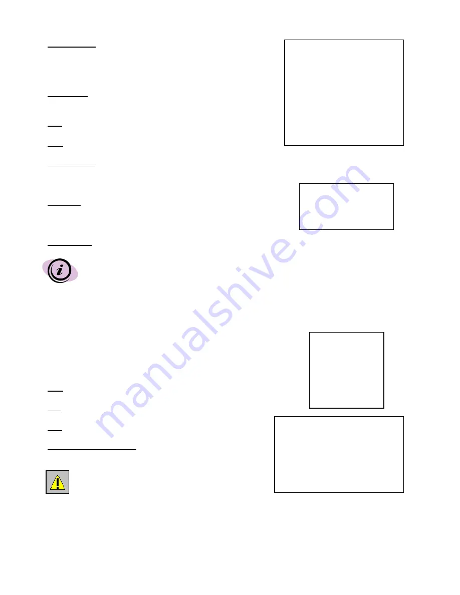
(System)

Buzzer : On 
HDD Overwrite : No
Message Latch: On
Date Display : Y- M - D
Date : 2002-JUL-14(SUN)
Time : 22:38:29
New Password : xxxx
Clear HDD : No
System Reset : No

All Data in HDD

Will Be Cleared

Are you sure?

(

: No 

: Yes )

The Date, Time and Password will not change after a System Reset.

EVENT

An “Event” occurs when 1 of 3 incidents occur: a loss in Power,
a loss in Video, or a HDD error.

This submenu displays a list of Events that disabled recording in 
order of their occurrence by Time and Date.

PWR

– The time that Power returned after a Power failure.

VLS

– The time that the Video input was lost.

HDD

– The time that the HDD experienced an error.

Page Up

Page Down

– Scroll between pages of Events 

by pressing the arrow buttons.

PWR 2002-JAN-01 03:00:00

VLS 2002-JAN-01 01:02:04

HDD 2002-JAN-01 01:02:03

PWR 2002-JAN-01 01:02:02

VLS 2002-JAN-01 01:02:01

HDD 2002-JAN-01 01:02:00

: Page Up 

: Page Down 

THE SYSTEM ONLY RECORDS A LOGGED EVENT 
WHEN THE EVENT OCCURS DURING RECORDING.

(Menu)

Timer
Record
Alarm
Remote
System

Event

12

Summary of Contents for DGR1100 Series

Page 1: ...eries DVR without Audio DXR1100 SXR1100 DGR1100 Series DVR with Audio Please be sure to read carefully and follow all the safety information Keep the manual in a safe place for future reference www st...

Page 2: ...ds of Fast Forward and Rewind to move slowly or rapidly To learn more about this system or to find out more about other products available please visit our website at www strategicvista com FEATURES D...

Page 3: ...ed service personnel This unit should be operated only from the type of power source indicated on the manufacturer s label This installation should conform to all local codes SAFETY WARNING CAUTION RI...

Page 4: ...E PROTOCOL 12 KEY LOCK 13 TROUBLESHOOTING 14 TECHNICAL SPECIFICATIONS 15 APPENDIX 1 INSTALLING THE HDD 16 APPENDIX 2 CONNECTION TO MONITOR 17 APPENDIX 3 ALARM BLOCK CONNECTION TO MONITOR 18 APPENDIX 4...

Page 5: ...zed and bold THIS TYPE OF COMMENT REPRESENTS SOMETHING TO BE AWARE OF OR TO BE CAUTIOUS ABOUT TEXT IS BOLD AND IN UPPERCASE SYSTEM INCLUDES Single channel DVR Hard Disk Drive not included with all mod...

Page 6: ...llowing messages HDD Detecting followed by Master HDD Connected Once connected the POWER LED will change to green color and red indicator lights be ON next to the Alarm and Timer buttons 2 IF YOU GET...

Page 7: ...me Date or Alarm For more information about the SEARCH options please see page 14 SLOW Press SLOW to slow down the speed of Play mode It can also be used to slow down the speed of Fast Forward and Rew...

Page 8: ...through options PAUSE The pause button serves two functions i Pressing PAUSE pauses the recorded video being played on screen ii In Menu mode the button is used to scroll Up through options PLAY Press...

Page 9: ...RNAL I O Connects to a PC for Remote Protocol or to the Alarm Block included with the system A motion sensor is required to connect to the Alarm Block POWER INPUT Connects to the Power cord 1 2 3 4 Ex...

Page 10: ...r Programs specific times that you want the DVR to record Record Controls the speed quality and mode of recording Alarm Programs Alarm duration and recording during an Alarm Remote Chooses interface f...

Page 11: ...TEM IS NOT NECESSARILY RECORDING SINCE IT WILL ONLY RECORD DURING ITS SCHEDULED TIME RECORD Record IPS Set the system to 60 Images Per Second to record in real time Other setting options are 30 15 8 4...

Page 12: ...32 or RS 485 interface for the remote computer connection protocol Please refer to Appendix 3 for PIN configuration and page 14 for more information on Remote Protocol Baud Rate Set the speed of the r...

Page 13: ...stem Buzzer On HDD Overwrite No Message Latch On Date Display Y M D Date 2002 JUL 14 SUN Time 22 38 29 New Password xxxx Clear HDD No System Reset No All Data in HDD Will Be Cleared Are you sure No Ye...

Page 14: ...TON The Jog Button allows you to manually view video frame by frame one image at a time While in PLAY mode press PAUSE While in Pause mode pressing the FF button advances the frozen screen one image f...

Page 15: ...by the next video in chronological order until it hits the End of the list You can stop the video at any time by pressing the STOP button RS232 REMOTE PROTOCOL The RS232 Alarm input allows you to con...

Page 16: ...stem is in Key Lock mode Press MENU and ENTER at the same time to escape the Key Lock mode Buttons aren t working when pressed Check the power source cord connections Check that there is power at the...

Page 17: ...e 1 Vp p 75ohm BNC VIDEO RESOLUTION 720 x 486 VIDEO COMPRESSION Wavelet DISPLAY REFRESH RATE 60 ips NTSC RECORD REFRESH RATE 60 ips NTSC ALARM INPUT TTL input High 5V Low GND ALARM OUTPUT COM NO VIDEO...

Page 18: ...ce YOU MAY FIND THAT THE CARTRIDGE CASING IS LOCKED IN THIS CASE SKIP AHEAD TO STEP 8 TO FIND INSTRUCTIONS ON UNLOCKING THE CABINET THEN RETURN TO STEP 2 2 17 Remove the Cartridge Casing from the DVR...

Page 19: ...cable is the standard Hard Drive IDE type connection 4 5 18 Secure the HDD in the Casing optional Use the six supplied screws and tighten them positioning the HDD into place This step is optional but...

Page 20: ...cabinet by turning the key clockwise If you need to unlock the cabinet turn the key counter clockwise from the position shown above IF YOU DO NOT LOCK THE CABINET THE DVR SYSTEM WILL NOT FUNCTION PROP...

Page 21: ...nection with a Multiplexer Connection with a Quad Monitor Note If using a TV it may have to be set in AUX mode sometimes referred to as TV Video Note Monitor may have to be set in VCR mode Shown below...

Page 22: ...NO 8 NC 7 R S 6 E O 5 S O 4 V L 3 TX1 2 RX1 1 15 COM 14 A I 12 D F 13 A R 11 RX2 10 TX2 9 GND GND Alarm Out DVR Back Panel Monitor Back Panel APPENDIX 3 ALARM BLOCK CONNECTION to MONITOR 21...

Page 23: ...3 TX1 2 RX1 1 15 COM 14 A I 12 D F 13 A R 11 RX2 10 TX2 9 GND GND DVR Back Panel Multiplexer Back Panel Please refer to your Multiplexer user manual for the switch out pin number APPENDIX 4 ALARM BLO...

Page 24: ...APPENDIX 5 PIN CONFIGURATIONS 23...

Page 25: ...h NO PIN 8 EXTERNAL ALARM NO Under normal operation COM connect with NC and disconnect with NO But when Alarm triggered COM disconnect with NC and connect with NO PIN 9 GND GROUND PIN 10 RS485 B DVR c...

Page 26: ...r rack mounting applications can be purchased as an optional accessory APPENDIX 6 RACK MOUNT INSTALLATION For more information about the rack mount other accessories through Strategic Vista please vis...

Page 27: ...5 Record High 12 24 49 92 185 370 740 Quality Normal 18 37 74 138 277 554 1108 Basic 30 61 123 231 463 926 1850 Based on 40 GB HDD IPS 60 30 15 8 4 2 1 Best 4 5 9 18 5 34 5 69 138 5 277 5 Record High...

Reviews: