background image

46

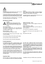
Fill the fuel oil tank with light fuel oil or diesel fuel.

Caution:

The oil pump may be damaged if the system is operated 

without having filled any fuel. Please ensure water does 

not reach the fuel oil tank (this will damage the oil pump).

Frost protection

Frost damages devices in which the water has not been 

completely drained. The best way to protect the device 

from frost is to store it in a frost-free place.

Do not direct the water jet at persons or animals (risk of 

injuries from pressure and heat).


Do not direct the water jet at the device or any other electri-

cal components (risk of short circuits and other damage).

Electrical connection

The voltage stated on the type plate must correspond to 

the power supply voltage. The power cable must be pro-

tected by a 16A fuse. Fuses with higher values are not per-

mitted. Install an RCD on site. Electrical connections and 

fusing must be implemented by specialists only.

Connect the device to sockets that have been correctly in-

stalled as per VDE and energy supplier regulations only. 

Exclusively electricians must perform work on electrical 

device components.

Additional safety precautions and instructions on hand-

ling electrical energy

1. Connect the device to correctly installed power supplies 

only.

2. Check the cables for damage before use.

3. Connections must be dry and must not lie on the ground.

4. Do not touch plugs with wet hands.

5. Any extension leads used must always be fully removed 

from the drum and have a sufficient cable diameter (2.5 

mm²) to prevent short circuits or the cable from overhea-

ting (scorching).

It is not permitted to use the device in explosive environ-

ments

Use suitable fuel only: fuel oil, light oil or diesel fuel.

Do not use unsuitable fuels, as this may cause risks, for 

instance the risk of explosion, deflagrations or risk of fire.

Operators must continuously monitor fuel-powered heating 

modules during operation.

Operation

Device switch to "O"

Temperature controller to "O"

Water supply

Connect high-pressure cleaners or water hoses to the con-

necting nipples indicated with "EIN".

Completely open the tap if the system is connected to a 

water pipe.

Water input pressure at minimum 4 bar, 9 l / min., at ma-

ximum 180 bar, 18 l / min.

Inlet side connection

Connect the high-pressure hose to the connection nipple 

indicated with "AUS".

Insert the device plug into the socket, open the water sup-

ply or switch on the high-pressure cleaner. Activate the 

shut-off cock at the heating coil outlet until a sufficient 

amount of water escapes. The device is now ready for ope-

ration.

Hot water operation

Set the device switch to the "1" position and switch the 

burner on. Set the desired operating temperature on the 

temperature controller.

Caution:

The maximum permissible temperature is 80° C if the de-

vice is operated with the Krake 80 high-pressure cleaner.

Switch to the "Brenner EIN" position to activate the burner 

and trigger continuous ignition at the trigger electrodes. 

The solenoid valve in the fuel oil supply switches on if wa-

ter is removed.

The solenoid valve immediately and automatically swit-

ches off upon closing the water jet. The temperature con-

troller and the flow monitor control the opening and closing 

of the solenoid valve.

Commissioning

Translation of the original instruction

Summary of Contents for Hot Box 240

Page 1: ...Hot Box 240 DE NL FR IT GB CZ...

Page 2: ...8 00 7 86 72 44 kostenloses Bestell Fax 08 00 7 86 72 43 nur innerhalb Deutschlands Lieferumfang Hotbox 240 2 m Hochdruckschlauch Bedienungsanleitung Inhaltsverzeichnis Seite Lieferumfang 2 Technische...

Page 3: ...beachten Sie auch dass Trink wasser mit geringer wasserh rte wasserf hrende Bauteile besch digen kann Bei Anschlu an die Stomversorgung beachten Sie bitte die Vorschriften des zust ndigen Energieverso...

Page 4: ...eraturregler Schaltet bei unzul ssiger berhitzung den L ftermotor Brenner ab Der F hler befindet sich auf der Kaltwasser seite vor der Brennkammer Wird beim Schliessen der Pistole der Brenner nicht ab...

Page 5: ...natige Wartung berpr fung UVV Pr fung des gesamten Heizmoduls Die Pr fung mu durch eine fachkundige Person durchge f hrt werden Die Ergebnisse der Pr fung sind schriftlich in einem Pr f protokoll fest...

Page 6: ...ein und einen ausreichenden Leitungsquerschnitt 2 5 mm aufweisen sonst kann es durch berhitzen des Kabels Schmoren zu einem Kurzschlu kommen Ein Betrieb in explosionsgef hrdeten Zonen ist nicht zu l s...

Page 7: ...turregler zu gering eingestellt auf gew nschte Temperatur einstellen Temperaturregler defekt erneuern Gebl semotor l uft nicht Brennersicherung defekt erneuern Ursache feststellen Z ndung erfolgt nich...

Page 8: ...8 Detailzeichnung Einstellung der Z ndelektroden Originalanleitung...

Page 9: ...enmantel 5 Heizschlange 6 Zwischenplatte 7 Flammrohr 8 lleitung 9 Abdeckblech 10 Brennerd se 11 D senflansch 13 Z ndelekrode 22 Nippel 23 Magentventil 26 L fterrad 27 L fter mit Flansch 28 Madenschrau...

Page 10: ...r che bestehen ausschlie lich an Werkstoff oder Fertigungsfehler sowie ausschlie lich bei bestimmungsgem er Verwendung des Ger ts Verschlei teile fallen nicht unter die Garantieanspr che S mtliche Ans...

Page 11: ...G ltigkeit Bezeichnung des Ger tes Hot Box 240 Ger te Typ Hei wassermodul Artikel Nummer 65 03 00 Angewandte EG Richtlinien Maschinen Richtlinie 2006 42 EG Niederspannungs Richtlinie 2006 95 EG EG Ric...

Page 12: ...72 43 alleen binnen Duitsland Levering Hotbox 240 2 m hogedrukslang gebruiksaanwijzing Inhoudsopgave Pagina Levering 12 Technische gegevens 12 Algemene veiligheidsinstructies 13 15 Onderhoudsplan 15 P...

Page 13: ...en te zacht water onder 10 d h gebruiken Geen zoutwater gebruiken Geen agressieve chemicali n die niet ph neutraal zijn gebruiken Bij gebruik van bovengenoemde vloeistoffen kan er scha de ontstaan aan...

Page 14: ...entilatormotor brander uit bij niet toe laatbare oververhitting De voeler bevindt zich aan de kant van het koudwater voor de verbrandingskamer Wanneer de brander niet uitvalt bij het sluiten van het p...

Page 15: ...onderhoud jaarlijkse controle Controle op ongevalveiligheid van het volledige ver warmingselement De controle moet door een deskundige worden uitgevoerd De resultaten van de controle moeten worden ge...

Page 16: ...zijn en een voldoende diameter 2 5 mm2 hebben anders kan de kabel oververhit geraken verschroeien en kan dit tot kortsluiting leiden In zones met explosiegevaar mag niet gewerkt worden Enkel een gesc...

Page 17: ...gen Thermostaat is te laag ingesteld op gewenste temperatuur instellen Thermostaat kapot vervangen Ventilatoraandrijving werkt niet Branderveiligheid defect vervangen oorzaak vaststellen Er is geen on...

Page 18: ...18 Instelling van de ontstekeningselektroden Detailtekening Vertaling van de originele handleiding...

Page 19: ...5 Verwarmingsslang 6 Tussenplaat 7 Vlambuis 8 Olieleiding 9 Afdekplaat 10 Branderkop 11 Kopflens 13 Ontstekeningselektrode 22 Nippel 23 Magneetklep 26 Ventilatorwiel 27 Ventilator met flens 28 Stelbou...

Page 20: ...kening gebracht 49 0 202 49 20 110 Garantieclaims Claims uitsluitend met betrekking tot materiaal of productiefouten en uitsluitend bij gebruik van het apparaat conform de voorschriften Voor slijtdele...

Page 21: ...ding van het apparaat Hot Box 240 Apparaattype Heetwatermodule Artikelnummer 65 03 00 Toegepaste EG richtlijnen Machinerichtlijn 2006 42 EG Laagspanningsrichtlijn 2006 95 EG EG richtlijn Elektromagnet...

Page 22: ...mande gratuit 49 800 7 86 72 43 uniquement en Allemagne Table des mati res Page tendue des fournitures 22 Donn es techniques 22 Consignes de s curit g n rales 23 25 Plan de maintenance 25 Description...

Page 23: ...utiliser de produits chimiques agressifs qui n ont pas de ph neutre En cas d utilisation des liquides susmentionn s ceux ci peuvent causer un endommagement au niveau de tous les composants v hiculant...

Page 24: ...fe le thermostat d branche le moteur du ventilateur br leur La sonde se trouve c t eau froide devant la chambre de combustion Si le br leur ne s teint pas lors de la fermeture du pisto let de la vapeu...

Page 25: ...ification de l unit de chauffage dans son ensemble en fonction du r glement de pr voyance contre les accidents La v rification doit tre effectu e par un professionnel Les r sultats de cette v rificati...

Page 26: ...u d vidoir et la section du conducteur doit tre suffisante 2 5 mm pour viter la surchauffe du c ble carbonisation et par cons quent un court circuit Ne jamais utiliser l appareil dans une zone o il ex...

Page 27: ...rmostat Le moteur du ventilateur ne fonctionne pas Le fusible du br leur est d fectueux Remplacer le fusible d terminer la cause Pas d allumage Les lectrodes d amor age sont d r gl es R gler les lectr...

Page 28: ...28 Dessin d taill R glage des lectrodes d allumage Traduction des instructions d origine...

Page 29: ...que interm diaire 7 Tube de flamme 8 Conduite d huile 9 T le de couverture 10 Buse de br leur 11 Bride de buse 13 Electrode d allumage 22 Raccord filet 23 Electrovalve 26 Rotor 27 Ventilateur avec bri...

Page 30: ...Demande de prise en garantie Les demandes couvrent exclusivement les d fauts de mat riau ou d ouvrage et ne couvrent qu une utilisation conforme la destination de l appareil Les pi ces d usure ne sont...

Page 31: ...ox 240 Type d appareil Module d eau chaude R f rence article 65 03 00 Directives CE appliqu es Directive sur les machines 2006 42 CE Directive sur la basse tension 2006 95 CE Directive europ enne sur...

Page 32: ...la sicurezza 33 35 Programma di manutenzione 35 Descrizione del prodotto 35 Messa in funzione 36 37 Guasto Possibile causa Rimedio 37 Elenco ricambi Disegno dettagli Regolazione degli elettrodi di ac...

Page 33: ...lce durezza inferiore a 10 dH Non utilizzare acqua salata salamoia Non utilizzare sostanze chimiche aggressive dal ph non neutro L utilizzo dei liquidi sopramenzionati pu danneggiare tut ti i componen...

Page 34: ...anti alla camera di combustione Se chiudendo la pistola il bruciatore non viene disattivto si forma del vapore nella serpentina di riscaldamento che viene deviato attraverso la valvola di sicurezza Se...

Page 35: ...ficare la conformit alle norme antinfortunistiche dell intero modulo Il controllo deve essere affidato a personale competente ed i risultati riportati per iscritto in un verbale che va con servato Des...

Page 36: ...imenti si potrebbe generare un corto circui to per surriscaldamento del cavo fusione Non consentito far funzionare l apparecchio in luoghi a rischio di esplosione Utilizzare solo combustibili adatti o...

Page 37: ...latore difettoso Sostituirlo Il motore sovralimentato non funziona Il dispositivo di sicurezza del bruciatore difettoso Sostituirlo stabilire la causa La macchina non si accende Gli elettrodi di accen...

Page 38: ...38 Disegno dettagli Regolazione degli elettrodi di accensione Traduzione delle istruzioni originali...

Page 39: ...edia 7 Camera di combustione 8 Tubazione dell olio 9 Lamiera di copertura 10 Ugello del bruciatore 11 Flangia del bruciatore 13 Elettrodo di accensione 22 Nipplo 23 Elettrovalvola 26 Ventola 27 Ventol...

Page 40: ...vi preghiamo di inviarci il dispositivo in modo completo con fat tura franco nostro centro di logistica a Berka oppure ad una service station da noi autorizzata Si prega di consultare prima la Hotline...

Page 41: ...a validit Denominazione dell apparecchio Hot Box 240 Tipo di utensile Modulo acqua calda Numero articolo 65 03 00 Applicate direttive CE Direttiva macchine 2006 42 CE Direttiva sulla bassa tensione 20...

Page 42: ...available in Germany Scope of delivery Hotbox 240 2 m high pressure hose operating instructions Contents Page Scope of delivery 42 Technical data 42 General Safety Precautions 43 45 Maintenance schedu...

Page 43: ...nents such as the pump pres sure regulating valve and heating coil The warranty is rendered void in the event of using water other than drinking water Please also observe that parti cularly soft water...

Page 44: ...of impermissi ble overheating The sensor is on the cold water side upst ream of the combustion chamber Vapour develops within the heating coil if the burner is not switched off when the gun is closed...

Page 45: ...re vention regulations This check must be conducted by a specialist The results of this check must be documented in a test record Keep the test record safe Product description The STORCH Hot Box 240 i...

Page 46: ...ts or the cable from overhea ting scorching It is not permitted to use the device in explosive environ ments Use suitable fuel only fuel oil light oil or diesel fuel Do not use unsuitable fuels as thi...

Page 47: ...not set high enough Set to desired temperature Temperature controller faulty Replace Fan motor not active Burner fuse faulty Replace Determine cause System does not ignite Trigger electrodes incorrec...

Page 48: ...48 Detailed drawing Adjusting the trigger electrodes Translation of the original instruction...

Page 49: ...ting coil 6 Intermediate plate 7 Flame pipe 8 Oil pipe 9 Cover plate 10 Burner nozzle 11 Nozzle flange 13 Ignition electrode 22 Nipple 23 Solenoid valve 26 Fan wheel 27 Fan with flange 28 Grub screw 2...

Page 50: ...first 49 0 202 49 20 110 Your rights under our warranty or guarantee Claims can only be accepted for material defects or manufacturing errors and only assuming intended use of the appli ance Wear par...

Page 51: ...t Box 240 Machine Type Hot water module Item number 65 03 00 Applied EC directives Machinery Directive 2006 42 EC Low Voltage Directive 2006 95 EC EC Directive on Electromagnetic Compatibility 2004 10...

Page 52: ...line objedn vky 49 800 7 86 72 44 bezplatn fax objedn vky 49 800 7 86 72 43 pouze v N mecku Rozsah dod vky Hotbox 240 2 m vysokotlak hadice n vod k obsluze Obsah Strana Rozsah dod vky 52 Technick daje...

Page 53: ...mus b t podle prvn ho ustanoven spolkov ho z kona o ochran p ed imisemi jednou ro n kontrolov no Va m oblastn m komin kem ohledn dodr ov n mezn ch hod not K m en mus d t podn t provozovatel vysokot l...

Page 54: ...en Bezpe nostn regul tor teploty P i nep pustn m p eh t vypne motor v tr ku ho k idlo se nach z na stran studen vody p ed spalovac komorou Pokud se p i zav r n pistole ho k nevypne tak se vytvo p ra...

Page 55: ...ltra n vlo ku 12 m s n dr ba kontrola UVV kontrola cel ho topn ho modulu Kontrola mus b t provedena odborn m pracovn kem V sledky zkou ky kontroly je t eba p semn zaznamenat v protokolu o zkou ce Prot...

Page 56: ...vykazovat dostate n pr ez ve den 2 5 mm jinak m e p eh t m kabelu kva en m doj t ke zkratu Provoz v z n ch ohro en ch exploz nen p pustn Pou vejte pouze vhodn palivo topn olej EL nebo naftu Nepou vejt...

Page 57: ...nastavit na po adovanou teplotu Regul tor teploty je vadn vym nit Motor v tr ku neb Ji t n ho ku je vadn vym nit stanovit p inu Neprov d se zapalov n Zapalovac elektrody jsou nespr vn nasta veny nast...

Page 58: ...58 Podrobn v kres Nastaven zapalovac ch elektrod P eklad origin lu n vodu...

Page 59: ...spir la 6 Mezideska 7 Spalovac trubka 8 Olejov veden 9 Kryc plech 10 Tryska ho ku 11 P ruba trysky 13 Zapalovac elektroda 22 Vsuvka 23 Magnetick ventil 26 Lopatkov kolo 27 V tr k s p rubou 28 Maden v...

Page 60: ...TORCH 49 0 202 49 20 110 N rok na z ruku p p garanci N roky na z ruku existuj v hradn u materi lu nebo v robn vady a tak v hradn p i pou v n p stroje v souladu s ur en m elem D ly podl haj c opot eben...

Page 61: ...na en za zen Hot Box 240 Typ n ad Modul pro horkou vodu V robek slo 65 03 00 Pou it sm rnice ES Sm rnice o stroj ch 2006 42 ES Sm rnice o n zk m nap t 2006 95 ES Sm rnice ES Elektromagnetick slu iteln...

Page 62: ...62...

Page 63: ...63...

Page 64: ...5 03 00 Hot Box 240 N art Denominazione 65 03 00 Hot Box 240 Art no Description 65 03 00 Hot Box 240 V r Ozna en 65 03 00 Hot Box 240 Malerwerkzeuge Profiger te GmbH Platz der Republik 6 8 D 42107 Wup...

Reviews: