
StorCase Technology, Inc.
RJR400 User’s Guide - Rev. C00
5
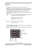
Front Panel
(Figure 2)
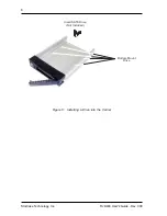
• Carrier Eject: Push to eject carrier from the receiving frame (Figure 3).
• Safety Lock: The safety lock assures proper seating of the drive carrier within the re-
ceiving frame and prevents accidental ejection of carrier. To lock, turn button 90° clock-
wise until horizontal. To unlock, turn button 90° counterclockwise until vertical.
• Power Switch (HD1 - HD4): Each drive carrier has its own power switch.
• Drive Activity LED (HD1 - HD4): Each power switch also acts as a Power and Drive
Activity LED.
NOTE:
Drive Activity LED feature supported by RJR400 Rev. C00 and up (rev.
level can be found on P/N label located on the unit).
Steady GREEN glow indicates power ON.
Flashing AMBER indicates drive activity.
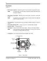
• Fan LED:
GREEN indicates that normal fan operation.
RED indicates fan failure.
• OverTemp LED/Reset: Flashing RED indicates overtemperature conditions (default is
60° C). Audible alarm will also sound.
Pushing this switch will reset OverTemp LED back to Green, as well as turn off audible
alarm.
Figure 2: Front Panel
Carrier
Handle
Safety
Lock
OverTemp LED
& Reset
Power Switch &
Power/Drive Activity LED
Fan
LED
Carrier
Eject


