background image

Introduction

1

SATA-to-USB 2.0 DE110 User's Guide - Rev. A00

StorCase Technology, Inc.

INTRODUCTION

Packaging Information

The StorCase Technology Data Express

®

 system is shipped in a container designed to provide

protection  and  prevent  damage  during  shipment.    The  Data  Express  unit  was  carefully

inspected before and during the packing procedure at the factory.  Bent or broken connectors,

or evidence of other damage to the Data Express should be reported to the shipper immediately.

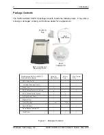
Refer to Figure 1 for the package contents.

If the wrong Data Express model has been received, please call your reseller or StorCase at

(800) 435-0642 to arrange for a Return Material Authorization (RMA).  StorCase cannot ac-

cept returns which do not display an RMA number on the outside of the package.  Return the

unit with all the original packing materials.

Before  removing  any  component  from  its  packaging,  discharge  any  static  electricity  by

touching a properly grounded metal object.

Serial Numbers

Both the DE110 receiving frame and carrier are labeled with serial numbers.  These numbers

must be reported to the StorCase Customer Service Representative in order to receive a Return

Material Authorization (RMA) for warranty claims.  Locate the serial number labels and record

the numbers in the spaces provided below.

Receiving Frame:

Device Carrier:

All manuals and user guides at all-guides.com

Summary of Contents for Data Express DE110

Page 1: ...StorCase Technology Data Express DE110 Removable SATA to USB 2 0 Drive Enclosure User s Guide All manuals and user guides at all guides com a l l g u i d e s c o m...

Page 2: ...Technology Inc 17600 Newhope Street Fountain Valley CA 92708 9885 Phone 714 438 1850 Fax 714 438 1847 StorCase Technology Data Express DE110 Removable SATA to USB 2 0 Drive Enclosure User s Guide Part...

Page 3: ...l StorCase interface cables and other accessories specifically intended for use with the StorCase products identified above are also covered by this 7 year warranty Three Year Warranty The following c...

Page 4: ...your system This warranty covers only repair or replacement of defective StorCase products as described above StorCase is not liable for and does not cover under warranty any costs associated with se...

Page 5: ...2 ITE Immunity IEC 61000 4 2 IEC 61000 4 5 IEC 61000 4 3 IEC 61000 4 6 IEC 61000 4 4 IEC 61000 4 8 IEC 61000 4 11 CAN CSA C22 2 No 950 95 UL 1950 EN 60950 2000 FCC Part 15 Class B AS NZS 3548 Informat...

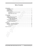
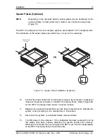
Page 6: ...Panel 6 INSTALLATION 8 Preparation 8 Installing the Drive into the Carrier 9 Universal Receiving Frame 11 Installing the Receiving Frame 11 Spacer Plates Optional 15 Selecting the Unit ID Number 16 U...

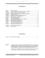
Page 7: ...re 10 Receiving Frame Mounting Holes 13 Figure 11 Connecting the Split USB Cable 14 Figure 12 Spacer Plate Installation Optional 15 Figure 13 Unit ID Select Switch Location 17 Figure A 1 DE110 Physica...

Page 8: ...your reseller or StorCase at 800 435 0642 to arrange for a Return Material Authorization RMA StorCase cannot ac cept returns which do not display an RMA number on the outside of the package Return the...

Page 9: ...Split USB Cable DE110 Carrier and Receiving Frame Dantz Software CD Data Express SATA to USB 2 0 Removable Enclosure Carrier Rec Frame Carrier Only Rec Frame Only SATA Drive Carrier Universal Receivi...

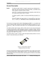
Page 10: ...oth support USB 2 0 For Windows 98 a driver down load is required at http www storcase com support firmware asp The StorCase Technology SATA to USB 2 0 Data Express DE110 is a removable drive carrier...

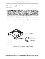
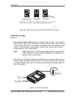
Page 11: ...nstalled but not Locked in the receiving frame a u will be displayed to indicateanunlockedcondition TheunitIDnumberisselectedbymeansoftheunitIDselect switch on the front of the receiving frame using a...

Page 12: ...key must be turned counterclockwise to the locked position NOTE Disable USB device on host computer desktop before turning OFF power simply right click on the Unplug Eject Hardware Icon located in th...

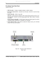
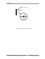
Page 13: ...per is factory installed on ID0 Change jumper position to Pins 3 4 for ID1 designation ID0 ID1 are for ID display purposes only Refer to Table 1 for further information Remote Activity LED RLED For PA...

Page 14: ...DE110 User s Guide Rev A00 StorCase Technology Inc Figure 5B Enlarged View of the Option Pins 1 2 ID0 Factory Installed Jumper Cathode Anode P13 P14 Remote Activity LED 13 14 ID1 3 4 All manuals and...

Page 15: ...d are re quired Windows 2000 XP both support USB 2 0 For Windows 98 a driver down load is required at http www storcase com support firmware asp Preparation NOTE A 2 Phillips screwdriver will be requi...

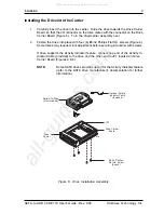
Page 16: ...minor adjustment before securing into carrier with screws If drive supports the Activity Indicator feature connect one end of the Activity In dicator Cable provided to the drive and the other end to J...

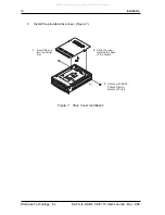
Page 17: ...v A00 Figure 7 Drive Cover Installation 0836 2 Slide the cover towards the back of the carrier 1 Insert this end into the carrier first 3 Secure with 6 32 Phillips Flat Hd screws 2 Total 3 Install the...

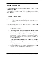
Page 18: ...rding to the manufacturer s instructions If neces sary temporarily remove any expansion boards that may make installation difficult 3 Locate the USB connector s on the system motherboard refer to your...

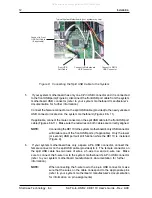
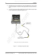
Page 19: ...B cable to the front USB port cable Figures 8 11 Make sure the red wires on both cables are correctly aligned NOTE ConnectingtheDE110tothesystemmotherboard sonlyUSBconnector will disable one of the fr...

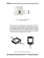
Page 20: ...o position the Data Express and fasten it into place with the four 4 6 32 Phillips screws provided Figure 10 illustrates the location of the mounting holes Mounting holes are provided on each side and...

Page 21: ...l units may require adjust ment 9 Connect the remaining end of the split USB cable to the DE110 USB connector located on the receiving frame motherboard Figures 5 11 Split USB Cable Connect to System...

Page 22: ...computer If the installation has been successful and all the cables have been properly attached the system should boot normally Although the computer may not recognize the DE110 yet the front panel di...

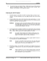
Page 23: ...amage to the drive 3 Use the alignment tool supplied with the DE110 to select the ID number of the disk drive Refer to Figure 13 for the location of the ID Select Switch inside the receiving frame Tab...

Page 24: ...ttings NOTE The unit ID number display is for ID display purposes only The following table lists the Unit ID Select Switch settings Please note that all invalid switch settings will result in a blank...

Page 25: ...Data Backup and Restoration NOTE The SATA to USB 2 0 DE110 includes a Dantz Retrospect Backup soft ware CD For easy data backup and restoration please refer to the Dantz User s Guide provided on the...

Page 26: ...Appendix A Specifications Dimensions 19 SATA to USB 2 0 DE110 User s Guide Rev A00 StorCase Technology Inc APPENDICES All manuals and user guides at all guides com a l l g u i d e s c o m...

Page 27: ...umidity 1 10 to 80 10 to 90 Altitude 1000 to 10 000 ft 1000 to 40 000 ft 305m to 3048m 305m to 12195m Shock 2 10g 60g 1 Non condensing with maximum gradient of 10 per hour 2 11 msec pulse width 1 2 si...

Page 28: ...0 DE110 Physical Dimensions Dimensions are for reference only Receiving Frame with Carrier Installed Carrier Only 0838A 4 73 120 1mm 1 52 38 6mm 1 75 44 5mm 3 75 95 3mm 7 939 201 65mm 3 12 79 2mm 5 81...

Page 29: ...ther in a safe impact and moisture resistant environment Its compact dimensions 10 long x 11 wide x 4 5 high make it easy to carry and to store The foam lining is contoured to fit a single Data Expres...

Page 30: ...uctions Everyone at StorCase Technology is working toward the goal of providing you with the highest quality most cost effective products available on the market and we need your comments to guide our...

Page 31: ...THIS LINE FROM BOTTOM TO TOP OF PAGE BUSINESS REPLY MAIL POSTAGE WILL BE PAID BY ADDRESSEE NO POSTAGE NECESSARY IF MAILED IN THE UNITED STATES FIRST CLASS MAIL PERMIT NO 10686 SANTA ANA CA TECHNOLOGY...

Reviews: