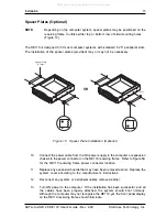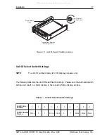
12
Installation
StorCase Technology, Inc.
SATA-to-USB 2.0 DE110 User's Guide - Rev. A00
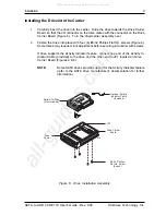
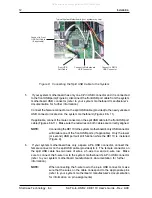
Connect to DE110
USB Connector
Front USB
Port Cable
Connect to Front
USB Port Cable
(If applicable)
Connect to Motherboard
USB Connector
Typical System Motherboard
(your system may vary)
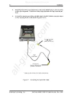
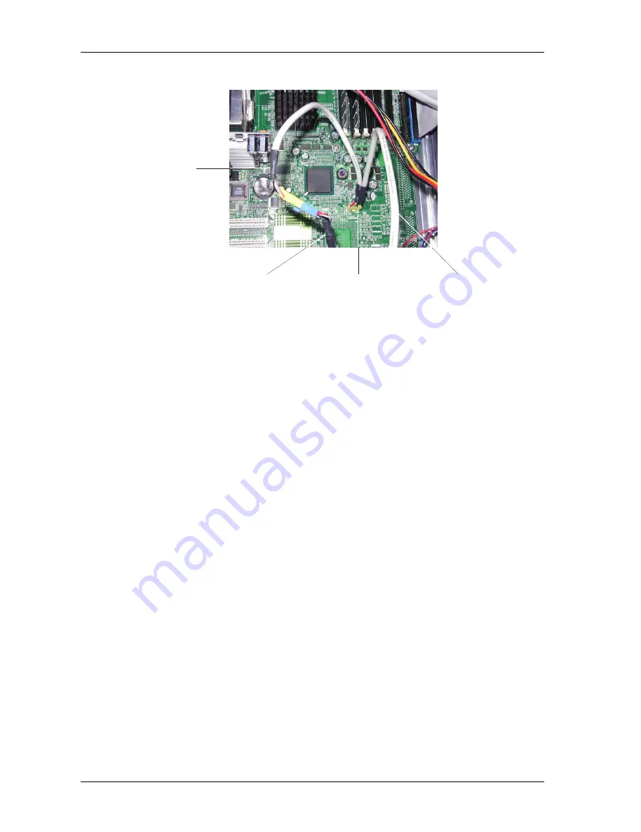
Figure 8: Connecting the Split USB Cable to the System
5.
If your system motherboard has only one 9-Pin USB connector and it is connected
to the front USB ports (Figure 9), disconnect the front USB port cable from the system
motherboard USB connector (refer to your system motherboard manufacturer's
documentation for further information).
Connect the female connector on the split USB cable (provided) to the newly vacated
USB connector located on the system motherboard (Figures 8 & 11).
If applicable, connect the male connector on the split USB cable to the front USB port
cable (Figures 8 & 11). Make sure the red wires on both cables are correctly aligned.
NOTE:
Connecting the DE110 to the system motherboard's only USB connector
will disable one of the front USB ports (if applicable). Only the lower
(or second) USB port will still function while the DE110 is installed
(Figure 9).
6.
If your system motherboard has only a spare 4-Pin USB connector, connect the
female connector on the split USB cable (provided) to it. The female connector on
the split USB cable has two rows of wires, a 5-wire row and a 4-wire row. Make
sure to connect the 5-wire row to the system motherboard's 4-Pin USB connector
(refer to your system motherboard manufacturer's documentation for further
information).
NOTE:
When connecting the 5-wire row to the 4-pin USB connector, make
sure that the wires on the cable correspond to the appropriate pins
(refer to your system motherboard manufacturer's documentation
for information on pin assignments).
All manuals and user guides at all-guides.com

