


7 AN 70 en
24
| Axiom AN
StoneL publication 105410revD
Image 5
O
R
P
S
T
X
Q
5.5
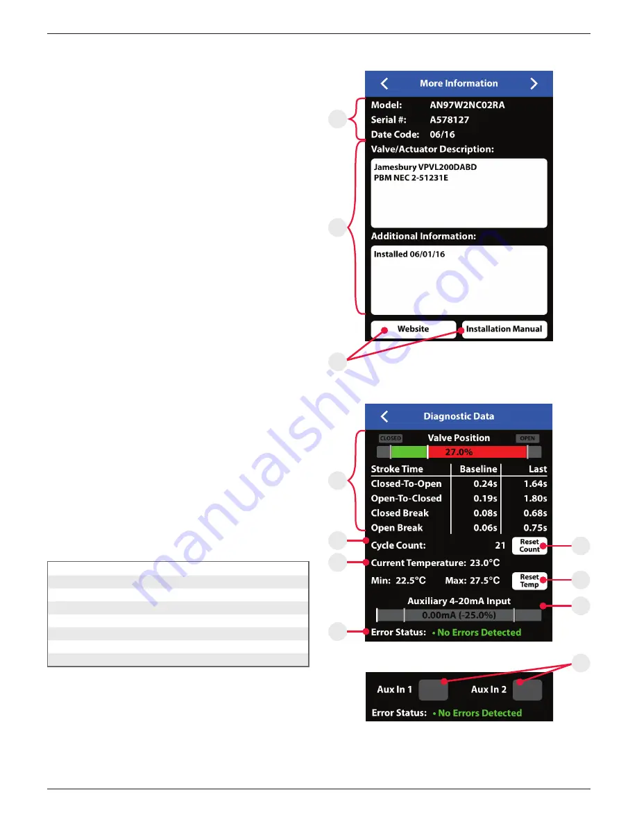
More information screen
To see additional information about a specific valve, swipe right or use
the arrows at the top of the device detail screen.
1. At the top of the more Information screen (Image 5), the unit
model number, serial number, and date code are displayed
(Item O). These are preset from the factory and cannot be
changed.
2. There are two customizable text boxes titled “Valve/Actuator
Description” and “Additional Information” where up to 160
characters can be added for user notes, such as maintenance or
service records (Item P).
Website and instruction manual
The direct links to StoneL’s website and the unit Installation,
Maintenance and Operating Instructions located on the bottom
buttons of the More Information screen require an internet
connection to access (Item Q).
5.6
Diagnostics screen
To see additional diagnostics about a specific valve, advance a page to
the right using the arrows at the top of the more information screen.
1. The valve position information includes real time valve position,
stroke time baseline, and stroke time of last cycle (Item R).
2. The valve cycle count is displayed and indicates how many cycles
the valve has made since last reset (Item S). A cycle is considered
to be a complete actuation of the valve. Selecting the reset button
(Item U) will erase the cycle count and start counting again from 0.
3. The current temperature of the valve monitor is displayed; along
with the temperature range of the valve since last reset (Item T).
Selecting the reset button (Item V) will erase the historical
temperature data and start a new period of temperature data
collection.
4. If an external 4-20mA loop powered device is connected to the
auxiliary analog input of the module, the feedback signal can be
monitored here. (DeviceNet only - Item W)
5. If external switches are connected to the Aux 1 or Aux 2 inputs of
the module, these switches can be monitored here. (AS-i only -
Item Y)
6. The Error Status register (Item X) can display numerous faults that
are detected by the module. This data is only available via the
Wireless Link app and is not accessible from the bus network. The
following is a list of errors/faults that can be detected and display
on the iOS device:
Error status register
Common
DeviceNet only
ASi only
Output shorted
Major DeviceNet fault
No data exchange
Internal sensor fault
Minor DeviceNet fault
No magnet detected
DeviceNet timed-out
Bus protocol error
Pending DeviceNet change
Duplicate address
Bus-off fault
Image 6a - DeviceNet detail
Image 6b - ASi detail
V
W
U
Y