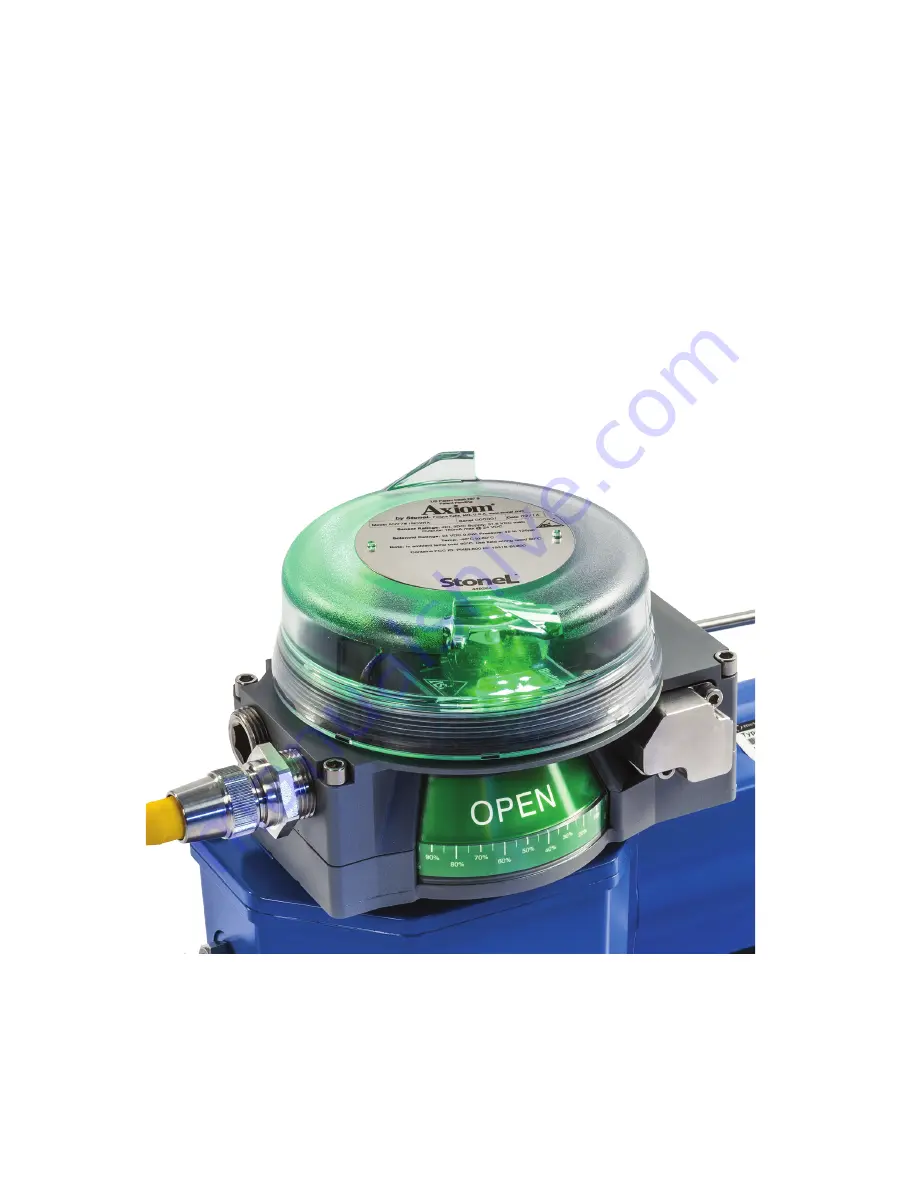
Axiom
™
AN by StoneL
Installation, maintenance and
operating instructions
StoneL publication 105410revD
7 AN 70 en – 03/2021
Page 1: ...Axiom AN by StoneL Installation maintenance and operating instructions StoneL publication 105410revD 7 AN 70 en 03 2021...
Page 2: ...m AN assembly figure 8 3 Maintenance repair and installation 9 3 1 Maintenance and repair 9 3 2 Installation 9 3 3 Specific conditions of use 9 4 Function specific details 10 4 1 Sensor switching modu...
Page 3: ...rtain about the use of this device or its suitability for your intended use please contact StoneL for assistance 1 3 CE markings The limit switch meets the requirements of European Directives and has...
Page 4: ...istance from original set point where switch will de energize Max rotational range 120 Terminal block specifications Recommended torque 4 42 in lbs 0 5 Nm Conductor strip length 0 22 0 25 in 5 5 6 5 m...
Page 5: ...luminum Polysulfone Nitrile compound Nitrile compound 316 stainless steel Solenoid coil specifications 35S 35W Operating voltage Power consumption Inrush current Filtration requirements 20 250 VAC 50...
Page 6: ...Dimensions Note Axiom AN certified dimensional drawing can be found at www stonel com E3 E2 S1 1 4 NPT 3 0 8 Cv or 3 8 NPT 3 1 2 Cv 1 2 NPT 2 M20 2 3 4 NPT 2 or M25 2 2 3 4 90 in 125 mm 1 4 NPT 2 2 48...
Page 7: ...the visual indicator drum retaining screw Item E Leave screw loose in order to facilitate indexing of the visual indicator 4 With the actuator in the closed position center the visual indicator drum...
Page 8: ...ug Internal ground lug provided C Body screws 4 D Trigger E Visual indicator drum retaining screw F Visual indicator drum G Visual indicator drum coupler H Visual indicator drive block I Air manifold...
Page 9: ...d a minimum of 1 4 turn after cover engages o ring Do not use any tool to tighten the cover WARNING Solenoid power supplied must be limited with a fuse or circuit breaker rated to 2 Amps maximum Field...
Page 10: ...WR 2 Solenoid 1 Power Open Closed Manual Solenoid 2 Power SET OPEN SET CLOSED OPEN NO OPEN C CLOSED NO CLOSED C SOL 2 PWR 1 SOL 2 PWR 2 1 2 3 4 5 6 7 8 Setup Instructions Operate actuator to closed po...
Page 11: ...odule operation 4 1 1 SST N O sensor 35S 35W continued Specifications for Wireless Link Communication Bluetooth technology single mode not compatible with Bluetooth Classic Frequency band 2 402 2 480...
Page 12: ...or single coil unit NAMUR SOL PWR SOL PWR Solenoid Power Closed Open Manual SET OPEN SET CLOSED not used OPEN OPEN not used CLOSED CLOSED 1 2 3 4 5 6 7 8 Setup Instructions Operate actuator to closed...
Page 13: ...1 Power Closed Open Manual SET OPEN SET CLOSED not used OPEN OPEN not used CLOSED CLOSED 1 2 3 4 5 6 7 8 Setup Instructions Operate actuator to closed position and touch SET CLOSED for 2 seconds Oper...
Page 14: ...tting instructions Power must be applied to both sensors to ensure proper circuit operation Use a 24 VDC power supply A series load resistor is not required when bench testing 1 Connect 24 VDC to the...
Page 15: ...StoneL publication 105410revD 7 AN 70 en Axiom AN 15...
Page 16: ...are assigned Default baud rate 125K software selectable 125K 250K or 500K baud Messaging Polling cyclic and change of state DeviceNet type 100 Bit mapping Inputs 3 bytes Byte 0 bit 0 red LED valve clo...
Page 17: ...t 2 to 1 in the desired unit Once the correct unit has been physically located on the network indicated by the winking of the LEDs set byte 0 bit 2 back to 0 Performing this function will not change t...
Page 18: ...D F IO 4 ID1 F ID2 E S 4 F E Bit assignment Inputs Bit 0 aux input 1 Bit 1 aux input 2 Bit 2 green LED valve open Bit 3 red LED valve closed Outputs Bit 0 not used Bit 1 not used Bit 2 OUT 1 Bit 3 OUT...
Page 19: ...open position 5 Press and hold SET OPEN button until green LED is lit 2 seconds Release button 6 Setpoints are retained even after power is removed A functioning AS Interface network is required to t...
Page 20: ...ID2 E S 7 A E Bit assignment Inputs Bit 0 red LED valve closed Bit 1 green LED valve open Bit 2 aux input 1 Bit 3 aux input 2 Outputs Bit 0 OUT 1 Bit 1 OUT 2 Bit 2 wireless link enabled Bit 3 not ava...
Page 21: ...er Solid green Normal operation Flashing red green Output shorted Flashing red green No magnet detected Flashing red green Internal sensor fault sensor may need replacing Flashing yellow red No data e...
Page 22: ...le 2 The device list export allows you to export valve tag number device address baud rate if applicable valve actuator description valve position stroke time cycle count data and additional informati...
Page 23: ...mplement changes made to the device address and or device baud rate Changing the device tag or address on an ASi unit 1 To change the tag edit the existing tag in the associated text field Item M The...
Page 24: ...ates how many cycles the valve has made since last reset Item S A cycle is considered to be a complete actuation of the valve Selecting the reset button Item U will erase the cycle count and start cou...
Page 25: ...user body or set the device to lower output power if such function is available This transmitter must not be co located or operating in conjunction with any other antenna or transmitter 5 7 2 Industri...
Page 26: ...hing internal override 0 8 Cv E Internal momentary override only 1 2 Cv Y External momentary internal override 1 2 Cv G External latching internal override 1 2 Cv X Special ENCLOSURE Clear cover Alumi...
Page 27: ...EN 62026 3 2009 EN 62311 2008 EN 62479 2010 EN 301 489 1 v2 2 0 2017 03 EN 301 489 17 v3 2 0 2017 03 EN 300 328 v2 2 2 2019 07 2809 ATEX II 2 G Ex db IIC T5 Gb ATEX II 2 G Ex db IIC T6 Gb ANX Series...
Page 28: ...emale cordset and the use of tool secured Turck lokfast guard is required ANabcdefg h Valve Position Monitor When e Connector 10 11 13 15 18 19 20 21 or 22 The Turck minifast and eurofast male recepta...
Page 29: ...uity between conduit and ground terminal 9 Resistance between Intrinsic Safe Ground and earth ground must be less than one ohm Specific Conditions of Use 1 Part of the enclosure is constructed from pl...
Page 30: ...ce between Intrinsic Safe Ground and earth ground must be less than one ohm Specific Conditions of Use 1 Part of the enclosure is constructed from plastic To prevent the risk of electrostatic sparking...
Page 31: ...lectrical continuity between conduit and ground terminal 9 Resistance between Intrinsic Safe Ground and earth ground must be less than one ohm Specific Conditions of Use 1 Part of the enclosure is con...
Page 32: ...A Tel 1 218 739 5774 stonel com Subject to change without prior notice Neles Jamesbury and Easyflow by Neles StoneL and certain other trademarks are either registered trademarks or trademarks of Neles...