14
3.2 HYDRAULIC CONNECTION
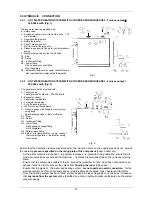
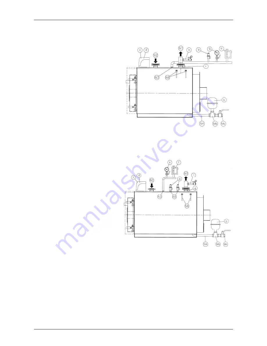
3.2.1 HOT WATER HEATING SYSTEM WITH CLOSED EXPANSION VESSEL - Furnace output
300.000 kcal/h (Fig. 1)
3.2.2 HOT WATER HEATING SYSTEM WITH CLOSED EXPANSION VESSEL - Furnace output >
300,000 kcal/h (Fig. 2)
Ensure that the hydraulic pressure measured after the reduction valve on the supply pipe does not exceed
the operating
pressure specified on the rating plate of the component
(boiler, heater etc.).
As the water contained in the heat ing system increases in pressure during operation, ensure that its
maximum value does not exceed the maximum hydraulic pressure specified on the component rating
plate.
Ensure that the safety valve outlets of the bo iler and hot water tank, if any, have been connected to an
exhaust funnel in order to prevent the valves from
flooding the room
if they open
.
Ensure that the pipes of the water and heating system
are not used as an earth connection
for the
electrical system as this can seriously and very rapidly damage the pipes, boiler, heater and radiators.
Once the heating system has been f illed, you are advised to close t he supply cock and keep it closed so
that
any leaks from the system
will be identified by a drop in hydraulic pressure indicated on the system
pressure gauge.
The generator must be provided with:
a - Safety valve
b - Expansion vessel (connected with a hose
18
mm diameter)
c - Regulation thermostats
d - Safety thermostat
e - Cut-off pressure switch
f - Well for control thermometer
g - Pressure gauge w ith flange for control pressure
gauge
h - Heat discharge valve or fuel on-off valve.
N1 - Flow
N2 - Return
N3 – Instrument fitting
N4 – Lower fitting:
N4b expansion vessel fitting
N4c filling/drain
N6 - Bulb wells (thermometer, pump consent thermo-
stat, regulation thermostat, safety thermostat).
The generator must be provided with:
a - 1 safety valve
2 safety valves if output is > 500,000 kcal/h
b - Expansion vessel
c - Regulation thermostats
d - 1st safety thermostat
f - Cut-off pressure switch
g - Well for control thermometer
h - Pressure gauge w ith flange for control pres-
sure gauge
i - Heat discharge valve or fuel on-off valve
N1 - Flow
N2 - Return
N3 - Instrument fitting
N4 - Lower fitting:
N4b expansion vessel fitting
N4c Filling/drain
N5 - Safety valves fitting
N6 -Bulb w ells (thermometer, pump consent
thermostat, regulation thermostat, safety
thermostat)
Fig. 2
Fig. 1
Summary of Contents for REX F
Page 1: ...TECHNICAL MANUAL REX REX F REX K REX K F REX DUAL REX DUAL F PRESSURISED STEEL BOILERS...
Page 2: ......
Page 18: ...18 1 2 6 3 4 5 9...
Page 30: ......
Page 32: ...ASSEMBLY INSTRUCTIONS STAVES LINING...
Page 33: ......


