background image

Section Description 

Page


Description and Specifi cations

 1.1 

Description 

.................................................................................................. 1

 1.2 

Specifi cations ............................................................................................. 2

 2 

Installation 

Instructions

 2.1 

Safety 

Precautions 

..................................................................................... 5

 2.2 

Shipment 

and 

Transit 

.................................................................................. 5

 2.3 

Machine 

Installation 

.................................................................................... 5


Initial Set-Up and Operation


3.1 

Operator’s Safety Precautions .................................................................... 7


3.2 

Operating Controls and Indicators .............................................................. 7

 3.3 

Sanitizing 

.................................................................................................... 8


3.4 

Freeze Down and Operation ...................................................................... 9

 3.5 

Mix 

Information 

........................................................................................... 9


3.6 

Removing Mix From Machine ..................................................................... 10


3.7 

Cleaning the Machine ................................................................................. 10


3.8 

Disassembly of Machine Parts ................................................................... 10


3.9 

Cleaning the Machine Parts ....................................................................... 11


3.10 

Sanitize Machine and Machine Parts ......................................................... 11


3.11 

Assembly of Machine ................................................................................. 11

 3.12 

Routine 

Cleaning 

........................................................................................ 12

 3.13 

Preventative 

Maintenance 

.......................................................................... 12

 3.14 

Extended 

Storage 

....................................................................................... 15

 4 

Troubleshooting

 4.1 

Light 

Indicators 

........................................................................................... 17

 4.2 

Troubleshooting 

.......................................................................................... 17

 5 

Replacement 

Parts


5.1 

Decals and Lubrication ............................................................................... 19


5.2 

Auger Shaft and Faceplate Parts ............................................................... 20

 5.3 

Hopper 

Parts 

.............................................................................................. 22

 5.4 

Autofi ll Options ........................................................................................... 23

TABLE OF

CONTENTS

Summary of Contents for E112

Page 1: ...Model E112 F112 OPERATORS MANUAL Manual No 513613 Rev 7...

Page 2: ......

Page 3: ...built prior to date of change DO NOT ATTEMPT to operate the machine until instructions and safety precautions in this manual are read completely and are thoroughly understood If problems develop or q...

Page 4: ...ecific safety information the following safety defini tions are provided to assist the reader The purpose of safety symbols is to attract your at tention to possible dangers The safety symbols and the...

Page 5: ...wn and Operation 9 3 5 Mix Information 9 3 6 Removing Mix From Machine 10 3 7 Cleaning the Machine 10 3 8 Disassembly of Machine Parts 10 3 9 Cleaning the Machine Parts 11 3 10 Sanitize Machine and Ma...

Page 6: ......

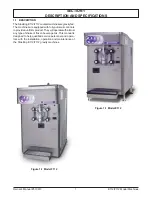
Page 7: ...he machines are equipped with fully automatic controls toprovideauniformproduct Theywilloperatewithalmost any type of shake or frozen beverage mix This manual is designed to help qualified service per...

Page 8: ...Owner s Manual 513613 2 E112 F112 Model Machines Figure 1 2 Specifications E112 F112 1 2 SPECIFICATIONS...

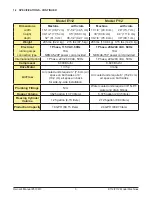
Page 9: ...cord provided NEMA6 15P power cord provided International Option 1 Phase 220 240 VAC 50Hz 1 Phase 220 240 VAC 50Hz Compressor 6 000 Btu hr 8 600 Btu hr Drive Motor 1 3 hp 3 4 hp Air Flow Air cooled un...

Page 10: ...Owner s Manual 513613 4 E112 F112 Model Machines...

Page 11: ...d later advise the carrier within 10 days and request inspection The customer must place claim for damages and or shortages in shipment with the carrier Stoelting Inc cannot make any claims against th...

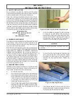
Page 12: ...power cord to the proper power supply The plug on the E112 is designed for 115VAC 20 amp duty and the plug on the F112 isdesignedfor208 240VAC 15ampduty Check thenameplateonyourmachineforpropersupply...

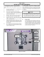
Page 13: ...r has been disconnected G Donotoperateunderunsafeoperatingconditions Neveroperatethemachineifunusualorexcessive noise or vibration occurs 3 2 OPERATING CONTROLS AND INDICATORS Before operating the mac...

Page 14: ...to Section 5 4 for Autofill options H Light Kit Optional E112 Part 2183800 F112 Part 2187102 The light kit is installed behind the header panel and illuminates a translucent header panel I Bottle Rac...

Page 15: ...a small amount of mix to remove any remaining sanitizer D Fill the hopper with pre chilled 40 F or 4 C mix NOTE Do not overfill the hopper Mix level must be below the air inlet tube on the mix inlet...

Page 16: ...r the spigot to catch the water When the water has drained place the switch in the OFF middle position Allow the freezing cylinder to drain completely E Prepare sanitizing solution according to manufa...

Page 17: ...ions to provide a 100 ppm strength solution Mix the sanitizer in quantities of no less than 2 gallons of 90 to 110 F 32 to 43 C water Check the strength of the sanitizing solution Use a chlorine test...

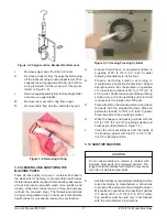
Page 18: ...C Put a small amount of spline lubricant on the hex end of the auger shaft Asmall container of spline lubricant is shipped with the machine D Install the plastic auger blade onto the auger E Push the...

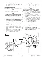
Page 19: ...EM In addition to food safety milkstone can cause premature wear to machine parts which can add to costs for replace ment parts or possibly more expensive repairs if worn machine parts are not replace...

Page 20: ...e of the test strip dispenser to determine the approximate chlorine concentration The ideal concentration of chlorine needs to be 100 ppm as stated by the FDA NOTE Follow the directions on the contain...

Page 21: ...ndenser needs a cool clean supply of water to properly cool the machine Inlet and discharge lines must be 3 8 I D minimum Make sure the machine is receiving an unrestricted supply of cold clean water...

Page 22: ...Owner s Manual 513613 16 E112 F112 Model Machines...

Page 23: ...current with another 3 second pre stir After the third attempt the compressor will run on timers N A Operation Every 7 minutes the auger will run for 90 seconds Timers or until torque switch remains...

Page 24: ...middle position for 15 minutes then restart Drive belt slipping or squealing 1 Worn drive belt 2 Freeze up Auger will not turn 3 Not tensioned properly 1 Replace drive belt 2 Turn CLEAN OFF ON switch...

Page 25: ...cal Caution Rotating Blades 1 1 324208 Decal Attention Refrigerant Leak Check 1 1 324393 Decal Stoelting Swirl Logo 1 1 324509 Decal Cleaning Instructions 1 1 324548 Decal Adequate Ventilation 6 1 324...

Page 26: ...all versions of the E112 and F112 Refer to page 21 to view the complete listing 630053 2183739 624645 624644 336551 2183099 570196 624545 625310 E112 2202181 F112 2202068 2183444 E112 2187600 F112 218...

Page 27: ...Rear Seal Black 5 Pack 1 1 625310 Quad Ring Front Door Black 1 1 630053 Rod Torque Actuator 1 1 666786 Seal Rear Auger Black 1 1 2183099 Breaker Bar Spigot Body 1 1 2183100 Blade Scraper E112 Ser 0 22...

Page 28: ...1 shake only 1 695714 Spring Consistency Adjustment Red 1 shake only 744252 Tray Drain 18 3 8 Long 1 744254 Tray Drip E112 Ser 24587 Plus F112 All 1 1 744273 Tray Drip E112 Ser 0 24586 1 744281 Tray...

Page 29: ...I is powered by gas and pumps up to 45 gallons per hour Fill O Matic II Fill O Matic III Fill O Matic II Part Numbers Autofill System 4177349 E112 Autofill Kit 2183807 F112 Autofill Kit 2187101 Usage...

Page 30: ...Owner s Manual 513613 24 E112 F112 Model Machines...

Page 31: ...se obligations remedies are subject to the conditions that Buyer a signs and returns to Stoelting upon installation the Start Up and Training Checklist for the affected equipment b gives Stoelting pro...

Page 32: ...ed to hoses piping or electrical equipment e Labor and travel charges due to return trips or waiting if the Authorized Stoelting Provider is prevented from promptly starting service work upon arrival...

Reviews: