background image

7

SECTION 3

INITIAL SETUP AND OPERATION

3.1 OPERATOR'S SAFETY PRECAUTIONS

SAFE OPERATION IS NO ACCIDENT; Observe these
rules:

A.

Know the freezer. 

Read and understand the

Operating Instructions.

B.

Notice all warning labels on the freezer.

C.

Wear proper clothing. 

Avoid loose fitting gar-

ments, and remove watches, rings or jewelry which
could cause a serious accident.

D.

Maintain a clean work area.

 Avoid accidents by

cleaning up the area and keeping it clean.

E.

Stay alert at all times. 

Know which switch, push

button or control you are about to use and what
effect it is going to have.

F.

Disconnect electrical cord for maintenance.

Never attempt to repair or perform maintenance on
the freezer until the main electrical power has been
disconnected.

G.

Do not operate under unsafe operating condi-
tions.

 Never operate the freezer if unusual or exces-

sive noise or vibration occurs.

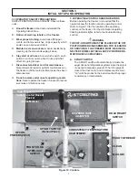
3.2 OPERATING CONTROLS AND INDICATORS

Before operating the freezer, it is required that the
operator know the function of each operating control.
Refer to Figure 10 for the location of the operating
controls on the freezer. For the information regarding
flashing indicator lights, refer to the troubleshooting
section.

WARNING

THE OFF-ON SWITCH MUST BE PLACED IN THE OFF
POSITION WHEN DISASSEMBLING FOR CLEANING
OR SERVICING. THE FREEZER MUST BE DISCON-
NECTED FROM ELECTRICAL SUPPLY BEFORE RE-
MOVING ANY ACCESS PANEL.

A. SPIGOT SWITCH

The SPIGOT switch will automatically  actuate the
auger drive and refrigeration systems when the spigot
is opened to dispense product. When the spigot is
closed, the drive motor and compressor will remain
"on" until the product in the barrel reaches the proper
consistency, or temperature.

Figure 10. Controls

High Pressure Cutout

Switch Located Back of

Freezer

(Some Models)

OFF-ON

POWER SWITCH

SPIGOT SWITCH

(Behind Panel)

HOLD READY

SWITCH

PUSH TO FREEZE

CLEAN

MIX LOW

CONSISTENCY/TEMPERATURE
ADJUSTMENT

DISPENSE RATE

ADJUSTER

FRONT DOOR

INTERLOCK

 SWITCH

Summary of Contents for 513588R1

Page 1: ...OPTIMA 111 OWNER S MANUAL Manual No 513588R1 Nov 2004...

Page 2: ......

Page 3: ...are certified in the Stoelting Technicare program Model No _______________________ Serial No _______________________ Purchase Date ____________________ Start Up Date ____________________ CALL Distrib...

Page 4: ......

Page 5: ...tions and specifications are not binding in detail We reserve the right to make changes to the freezer without notice and without incurring any obligation to modify or provide new parts for freezers b...

Page 6: ......

Page 7: ...tor s Safety Precautions 7 3 2 Operating Controls and Indicators 7 3 3 Sanitizing 8 3 4 Freeze Down and Operation 9 3 5 MixInformation 10 3 6 Removing Mix From Freezer 10 3 7 Cleaning The Freezer 11 3...

Page 8: ...11 Mix Inlet Regulator 9 12 CleanControl 9 13 SanitizingHopper 9 14 DrainingSolution 9 15 DispensingProduct 10 16 RemovingMixInletRegulator 10 17 DrainingMix 10 18 Auger Flight Wear Front Auger Suppo...

Page 9: ...to operate with almost any type of commercial soft serve or non dairy mixer available including ice milk ice cream yogurt and frozen dietary desserts This manual is designed to assist qualified servi...

Page 10: ...6 kg Crated 400 lbs 181 4 kg ELECTRICAL Description O111 Voltage AC 1 PH 208 230 Total Run Amps 12 70 Drive Motor 2 HP Use 20 amp HACR circuit breaker Automatic safeguard circuit built into electroni...

Page 11: ...life of the freezer Labels should be checked periodi cally to be sure they can be recognized as warning labels If danger warning or caution labels are needed indicate the part number type of label loc...

Page 12: ...he freezer at each corner to check for level condition If adjustment is necessary levelthefreezerbyturningthebottompartofeachleg in or out Then separate freezer base gasket and installwithseamtothebac...

Page 13: ...i tion NOTE Detailed instructions are included with each floor stand B Place a spirit level across the top of the stand to check for level condition side to side and front to back If adjustment is nec...

Page 14: ...6...

Page 15: ...urs 3 2OPERATINGCONTROLSANDINDICATORS Before operating the freezer it is required that the operator know the function of each operating control Refer to Figure 10 for the location of the operating con...

Page 16: ...X LOW LENS TheredMIXLOWlightisdesignedtoalerttheoperator to a low mix condition The lens will illuminate with approximately one gallon of mix in the hopper When the MIX LOW lens is lit refill hopper i...

Page 17: ...ANDOPERATION This section covers the recommended operating proce dures to be followed for the safe operation of the freezer A Sanitize just prior to use B Place the OFF ON switch in the OFF position C...

Page 18: ...uid mix Fig 17 D Place the OFF ON switch in the OFF position Figure 17 Draining Mix CAUTION REFRIGERATION IS AUTOMATICALLY ACTI VATED WHEN THE SPIGOT IS OPENED CLOSE THE SPIGOT COMPLETELY AFTER DISPEN...

Page 19: ...FF POSITION BEFORE DISASSEMBLING FOR CLEANING OR SERVICING Inspection for worn or broken parts should be made at every disassembly of the freezer for cleaning or other purposes All worn or broken part...

Page 20: ...arts refertothefollowingsteps NOTE Petro Gel sanitary lubricant or equivalent must be used when lubrication of parts is specified NOTE The United States Department of Agriculture and the Food and Drug...

Page 21: ...rel F Installtheremainingplasticflights pushtheaugerinto the freezer barrel and rotate slowly until the auger engagesthedriveshaft G Install the bushing and auger support into the front of the auger w...

Page 22: ...solution for an extended period of time more about delimers in Additional Information 3 13PREVENTIVEMAINTENANCE It is recommended that a maintenance schedule be fol lowed to keep the freezer clean and...

Page 23: ...ll become a problem if not remedied with additional products and procedures THE USE OF CHLORINE TEST STRIPS Test strips are used to determine concentrations of active chlorine in sanitizing solutions...

Page 24: ...one finger belt should deflect about 3 8 2 Lubricate condenser fan motor with S A E 20 weight oil Three to six drops is required CAUTION DO NOT OVER LUBRICATE RESULTING DAM AGE COULD CAUSE MOTOR FAIL...

Page 25: ...N 1 e r u l i a f t l e b e v i r D 2 e r u t a r e p m e t y c n e t s i s n o C 3 m r i f o o t s i g n i t t e s e r u t a r e p m e t y c n e t s i s n o C 4 e r u l i a f l o r t n o c x i m l i...

Page 26: ...i r d n r o W 1 n r u t t o n l l i w r e g u A p u e z e e r F 2 e c i v r e s r o f r o t u b i r t s i d l l a C 1 5 1 r o f F F O o t h c t i w s N O F F O n r u T 2 t r a t s e r n e h t s e t u...

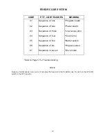
Page 27: ...of five Sequence of six Sequence of seven Program board Power board Low torque error Clean error Barrel sensor Hopper sensor Drive motor ERROR CODE SYSTEM Refer to Page 17 for Troubleshooting NOTE Fl...

Page 28: ...20...

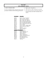
Page 29: ...diameter 208381 Brush 95cm 3 8 diameter 208467 Brush 80cm 5 16 diameter 324107 Decal Hazardous Moving Parts 324105 Decal Electrical Shock Hazard 324106 Decal Applicable Electrical Code 324108 Decal C...

Page 30: ...22 U 17 4...

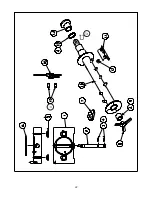
Page 31: ...t Rosette 8 3170644 1 Front Auger Support 9 149003 1 Bearing Front Auger Celecon 10 3156795 1 Auger 11 381804 5 Flight Loose Plastic Auger 12 694255 5 Spring Comp 13 624678 1 O Ring 1 1 2 x 1 1 8 x 3...

Page 32: ...24...

Page 33: ...Capillary Tube Drier Replacement 5 762448 1 Valve Expansion 1 2 Ton 6 762978 1 EPR Valve Green Label 7 762277 1 Check Valve Magni Chek 8 282032 SV 1 Compressor 208 230 60 1PH 9 284071 1 Condenser 2 Ro...

Page 34: ...26...

Page 35: ...26 4177556 1 Evaporator Weldment Foamed 27 M940077 As Reqd Epoxy Adhesive DP 110 Gray 3M 28 614232 1 Speed Reducer 5 2 1 Reduction 29 644605 4 Screw Cap 3 8 16 x 2 Hx Hd Zp Item Stoelting P N Qty Desc...

Page 36: ...28...

Page 37: ...brane Switch Black 31 649076 4 Screw Tap 8 32 x 3 8 Pan Hd Ph 32 766940 4 Washer Shakeproof 8 Zinc Plate 33 647393 5 Screw Mach 6 32 x 3 8 Rd Hd Ph Item Stoelting P N Qty Description 34 766933 8 Washe...

Page 38: ...30...

Page 39: ...Shock Hazard 21 324107 2 Decal Caution Hazardous Moving Parts 22 324208 1 Decal Attention Refrig Leak Check Item Stoelting P N Qty Description 23 324106 1 Decal Caution Wiring Mat l 24 M820309 As Req...

Page 40: ......

Page 41: ...ubject to the conditions that Buyer a signs and returns to Stoelting upon installation the Checklist Warranty Registration Card for the affected equipment b gives Stoelting prompt written notice of an...

Reviews: