Graphical User Interface description
UM2266
4/14
DocID030871 Rev 2
1
Graphical User Interface description
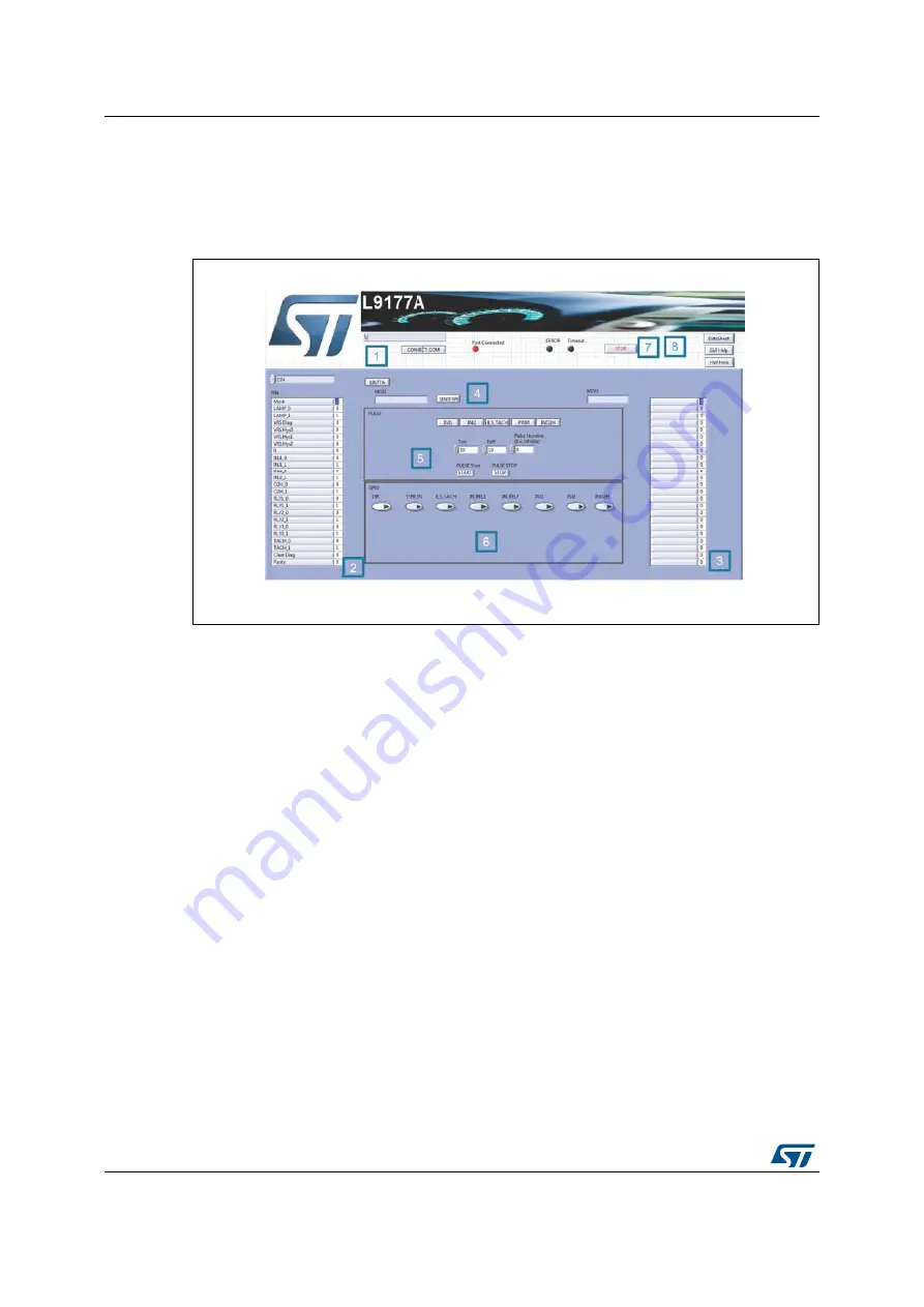
The L9177A GUI is made up by ten
fields:
Figure 1. GUI interface description
1.
Com Port Setup
: the COM port is automatically recognized once the GUI is launched
and the microcontroller board is correctly connected to PC and correct firmware is
present on it. In case of issue through the CONNECT COM button is possible to
manually select the microcontroller COM port.
2.
MOSI
: through this menu you can select the specific device register and set its required
value.
3.
MISO
: through this menu you can read the MOSI register of the device.
4.
SPI Send/Receive
: pushing the [
SEND SPI] button,
it is possible:
sending the SPI command configured in the MOSI menu(menu 2)
sending an SPI command manually written in the MOSI field.
reading the device answer MISO.
5.
PULSE
: using this field it is possible to generate a pulse train of a predetermined
number and duration on INJ1, INJ2, PWM, INO2H or ILS_TACH pins. Setting a value
of 0 in Pulse number the pulse generation starts and continues indefinitely until stop
button is pressed.
6.
GPIO:
this field allows the user to set the value of DIR, STEP_EN, ILS_TACH,
IN_REL1, IN_REL2, INO2H, PWM and INJ1 and INJ2
7.
STOP
button is used to stop the GUI
8.
Documentation button:
these buttons are used to have fast access to HW user
manual, GUI user manual, and L9177A datasheet


