In the STEVAL-GPT001V1 cradle board current limitation is set at 50 mA by R5 = 20 kΩ.
The red LED (CHRG), mounted between 5 V supply rail and STBC08PMR CHGR pin, remains activated until full
battery charge is achieved.
The STBC08PMR BAT output pin is connected to the battery through the
SPV1050TTR
STORE pin and the pass
transistor Q1.(As aforementioned this architecture allows full battery protection by avoiding over-voltage and
under-voltage events.)
1.4.4
Humidity and temperature sensor
The
HTS221
is an ultra-compact sensor for relative humidity and temperature measurement.
It includes a sensing element (manufactured using a proprietary ST process) and a mixed signal ASIC to provide
measurement data through digital serial interfaces.
The sensing element consists of a polymer dielectric planar capacitor structure capable of detecting relative
humidity variations and temperature.
The HTS221 is fully monitored by the firmware running on the SensorTile module; thus, the sensed values are
displayed by the app dedicated tab(For further details about HTS221, refer to the related datasheet freely
downloadable from www. st.com.).
1.4.5
STEVAL-GPT001V1 programming interface
When the SensorTile module is supplied (see
Section 1.4.3.1 Connection
,
Section 1.4.2 SensorTile module
connection
and
Section 1.4.1 Startup
) and connected to the
STEVAL-GPT001V1
cradle board or to the
STLCX01V1 SensorTile Cradle expansion board, the dedicated firmware STSW-GPT001V1 can be uploaded
through the SWD cable and an ST-Link programmer.
The easiest way is using an STM32 Nucleo board which bundles an ST-LINK V2.1 debugger and programmer.
Step 1.
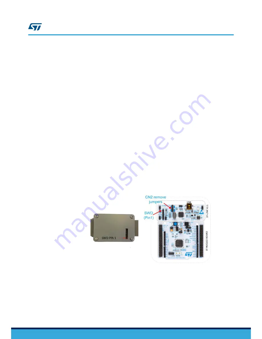
Ensure CN2 jumpers are OFF.
Step 2.
Connect your STM32 Nucleo board to the cradle, paying attention to the position of pin 1 on both SWD
connectors.
The STEVAL-GPT001V1 SWD connector is directly accessible from the cover back without opening
the case.
Figure 15.
STEVAL-GPT001V1 cradle board and STM32 Nucleo connection via SWD connectors
Step 3.
Connect the ST-LINK V2.1 to a USB port of a PC/laptop where the STM32 ST-LINK Utility is installed.
Step 4.
Launch the STM32 ST-LINK Utility and virtually connect it to the ST-LINK V2.1 ([
Target
]>[
Connect
]).
From [
File
]>[
Open
] you can browse your folder and select the file
STSW-GPT001V1.bin
.
Step 5.
Upload the firmware
STSW-GPT001V1.bin
([
Target
]>[
Program & Verify
]>[
Start address:
0x08004000
]).
Step 6.
Virtually disconnect the ST-Link V2.1 [
Target Disconnect
].
Step 7.
Disconnect the SWD cable from the cradle.
The uploaded firmware starts running automatically.
UM2260
UM2260
-
Rev 2
page 13/25


