background image

Main Control Unit

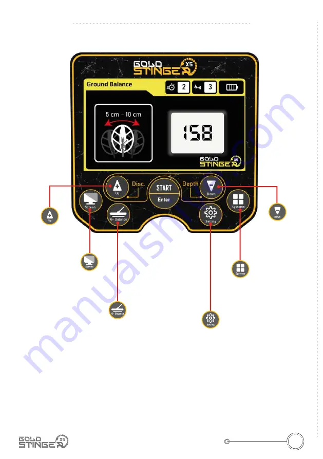
Up

The main control unit is the main part of the device through which we can 

control the device in general, as this unit enables us to access the detection 

modes of the device, its features and settings.

 The main control panel is located on the front of the main unit (system 

box), through which we can turn the device on and off, and it contains the 

charger and headphone sockets.

Main Unit

Se�ngs

User can use this bu�on to show 

general Se�ngs menu or screen

G-Balance

Used to enter to Ground Balance 

screen to adjust ground balance

Up / Disc.

- Move up in menu op�ons

- Change numbers and 

values

Systems

By clicking on this 

bu�on we can move 

to next detec�on 

system (mode) screen

Screen

Used to turn on/off 

screen backlight (this 

bu�on only works in 

Pin Pointer Mode)

Down / Depth 

- Move down between 

op�ons

- Change numbers and 

values

08

Main Control Unit

Overview

Summary of Contents for GOLD STINGER X5

Page 1: ......

Page 2: ...elcome...

Page 3: ......

Page 4: ...thod Main Unit User interface and coils Charging the device Correct usage methods Powering the device on Ground Balance All metal mode Discrimination Mode Pinpointer mode Gap test Depth detection Sepa...

Page 5: ...hroughout the world We are committed to provide the best quality and highest performance metal detectors for prospectors of all categories from beginners to professionals Stinger Detectors devices are...

Page 6: ...company guaran tees any results that fits the purpose intended by the user Stinger Detectors is not responsible for misunderstanding this manual or misusing the device Copyrights Gold Stinger X5 devi...

Page 7: ...r precious metals Important Notes about Ground Balance 1 When performing ground balancing for the first time do a factory reset of the device then install the appropriate search coil into the device c...

Page 8: ...ntents 3 Main unit with hand grip 2 GS 30 search coil GS 57 search coil Device charger Shafts x 2 5 Headphones 1 Cloth bag 2 Small size GS 30 search coil 3 Main unit system box with hand grip 4 Big si...

Page 9: ...e knob over the knob connection point clockwise Search Coil Installation Place the coil shaft appropriately on the coil Attach the search coil to the coil shaft using the screw and screw cap and then...

Page 10: ...on and off and it contains the charger and headphone sockets Main Unit Se ngs User can use this bu on to show general Se ngs menu or screen G Balance Used to enter to Ground Balance screen to adjust...

Page 11: ...32 x 26 cm dimensions used with 14 kHz frequency This coil is also suitable for use in areas such as rocks bushes walls and holes Big Size GS 57 Search Coil With 36 x 41 cm dimensions used with 7 kHz...

Page 12: ...e of a completely empty battery is about 5 hours Notes about Device Charging Notes when charging and not using the device The device should not be charged with a charger other than the main charger su...

Page 13: ...Correct Usage Methods Incorrect use Correct Use Correct usage Correct and incorrect use 11 Incorrect use Correct Use...

Page 14: ...me because the device automatically keeps the last ground balance in its memory Turn on the device with the button on the right side of the device main unit One of the search coils must be connected t...

Page 15: ...tton then the general settings screen will appear in grey as shown in the image above to enter the device settings we press the Enter Start button located in the center of the main control panel then...

Page 16: ...coil correctly and loading it into the device We lower the device from the air perpendicular to the ground so that the coil connected to the device is horizontal with the surface of the ground as sho...

Page 17: ...we are in the center point of the detected metal target All Metals Mode Metal and Void Detection All Metals Mode Void Detection When using the All Metals mode on the Gold Stinger X5 and while pass ing...

Page 18: ...After we detect the presence of metals by using All Metals Mode for example we can then move to the Discrimination mode by pressing the Up Disc button located on the left of the main control panel Di...

Page 19: ...example the device will makes a distinctive sound it will draw a yellow graph along with this sound indicating the signal strength captured when searching Note The device may give misleading signals i...

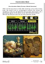
Page 20: ...as silver bronze brass and ancient coins or archaeological treasures like statues the inscriptions at the top will determine the precious metal option and a green graph appears on the device screen w...

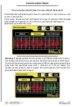
Page 21: ...ce of 5 10 cm above the surface of the ground and if it gives the same signals then make the ground balancing process again Discrimination Mode Non Precious Metals Detection If the detected metal duri...

Page 22: ...e the sound of the device reach the peak when the search coil passes the center of the buried target and the device reads the signals and translates them into digital values that change according to t...

Page 23: ...ell Sensitivity From here we can adjust the sensitivity of the device towards metals of all kinds Threshold Allows us to search with different and distinct sounds for each metal detected by the device...

Page 24: ...making any sound In order to enter the Gap Test mode we must press the Settings button in the main control panel and go to the Gap Test option in the device settings menu Note By defining the start a...

Page 25: ...n brown color when the device detects mineral soil without the device making any sound Note When the device start drawing the graph by defining the start and end points of the signal in the search are...

Page 26: ...another mark at the opposite end of it We repeat this process on the opposite side of the first process until we draw a square or rectangle shape around the target location then we take the estimated...

Page 27: ...rical value That could be due to not obtaining high accuracy or completely correct in the ground balance or not entering the target diameter of the target correctly Estimated Depth 300 cm is the estim...

Page 28: ...in the device we go to the device settings menu by pressing Settings button on the main control panel and then we can switch between the option to turn this feature on or off by selecting Non Preciou...

Page 29: ...the device can isolate non precious metals completely from the detection modes We can also access from the device settings the option to reset the device settings to the factory default values which...

Page 30: ...Fourthly Sound settings that enables us to adjust the overall sound volume of the device as we want Fifth Brightness settings that enable us to adjust the brightness value of device screen to be appro...

Page 31: ...all four sides of the place of search area until you make a rectangle or square area then you can enter the Depth Detection mode to determine the approximate depth of your buried target better When u...

Page 32: ...cm For 20 x 20 cm dimensions target the depth will be between 75 cm and 120 cm For 40 x 40 cm dimensions target approximate depth will be between 110 cm and 180 cm The maximum depth ranges from 200 c...

Page 33: ...System Embedded Special System Processor 32 Bit 7 Battery Working Time Standby 20 Hours 8 Battery Active Full Working Time 5 Hours 9 Operating Temperature Range 0 O C to 45 O C 32 O F to 113 O F 10 S...

Page 34: ...ts such as statues swords daggers weapons drinking glasses etc Prospecting for natural gold from gold nuggets and gold veins Discovering buried treasures such as golden chests valuable antiquities and...

Page 35: ......

Page 36: ...Thank you for choosing us...

Page 37: ......

Reviews: