STIHL 029, 039
68
11.6.
Automatic Choke
11.6.1
Description of Operation
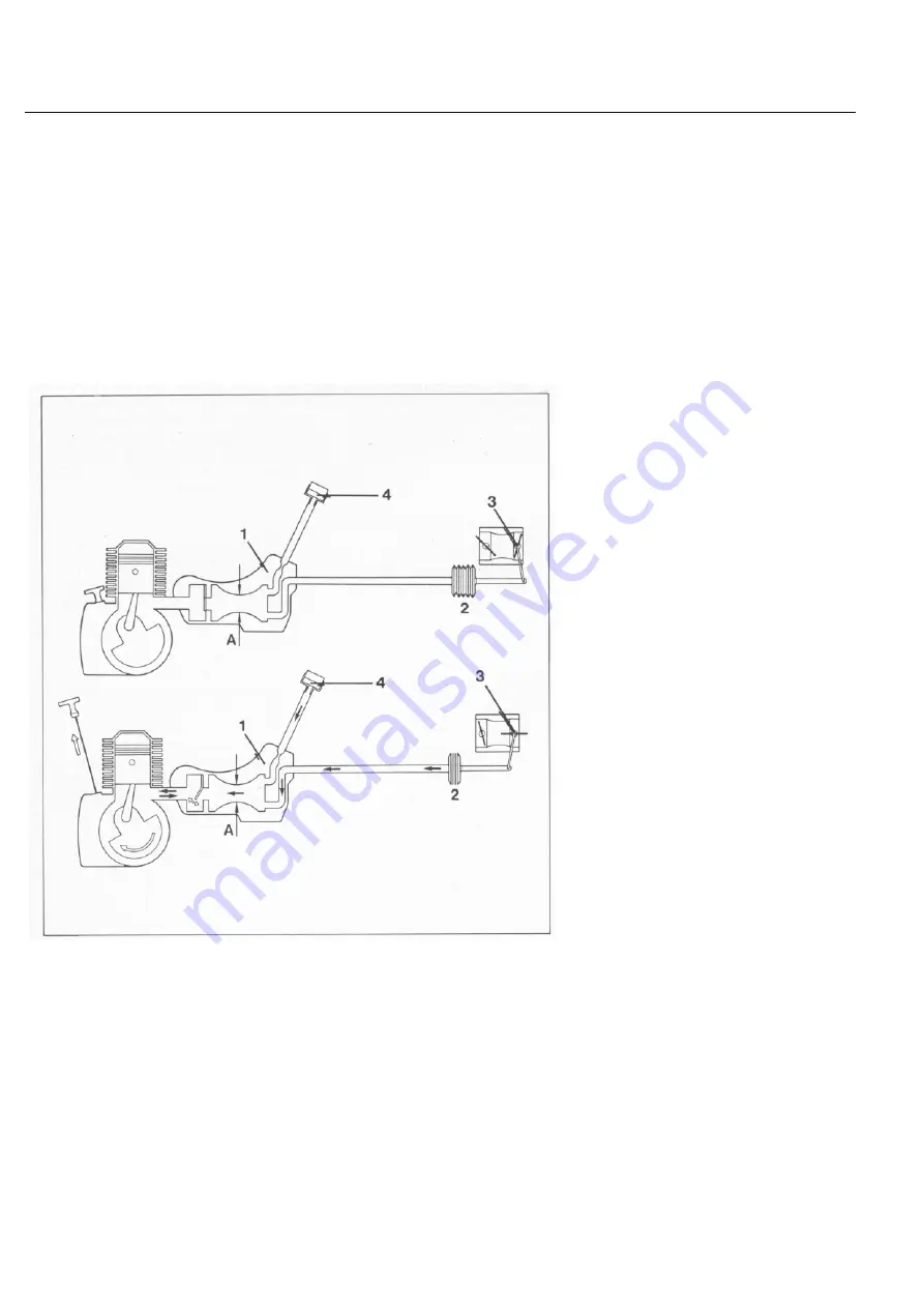
Schematic
1 = Control valve
2 = Bellows
3 = Choke shutter
4 = Sintered polymer and foam filter
A = Variable cross section
The bellows are located in the
handle housing. The period for
which the belows open the choke
shutter depends on cylinder tem-
perature. It varies between 3.5
seconds on a cold engine to approx.
0.1 seconds on a hot engine.
A system of levers connects the
choke shutter to the throttle shutter.
The throttle shutter is at an angle of
37 degrees to the carburetor
mounting flange just before the choke
shutter opens fully. The throttle
shutter returns to the idle position
when the choke shutter is fully open.
Following a starting attempt, the
bellows are filled with air from the
carburetor box and returned to the
neutral position. The air required to
pressurize the bellows is drawn in
from the carburetor box via a foam
filter, a polymer sintered filter, a hose
and control valve.
The pressurizing process is ac-
companied by a low whistling noise.
The polymer sintered filter and
foam filter are located in the area of
the handle housing.
A depression is maintained in the
bellows while the engine is running,
i.e. the bellows are contracted; the
choke shutter is open.
The regular changes in pressure
which occur in the engine housing
are used to operate the automatic
choke.
These variations in pressure are fed
via a cutout in the engine housing
and through a port in the cylinder to
the control valve.
The control valve feeds the low
pressure waves at a predetermined
interval to the bellows, which
contract and thus open the choke
shutter.
The automatic choke selects the
throttle and choke shutter positions
required for an optimum mixture.
It uses the cylinder temperature as a
parameter. Cross section "A" is
changed as a function of cylinder
temperature. This, in turn, alters the
time required to vent the bellows and
thus the opening speed of the choke
shutter.


