


iNSTALLATiON
installation
www.stiebel-eltron.com
WPL 47 | WPL 57 |
11
10.5 Filling the heating system
Carry out a fill water analysis before filling the system. This may,
for example, be requested by the relevant water supply utility.
!
Material losses
To avoid damage as a result of scaling, it may be neces-
sary to soften or desalinate the fill water. Always observe
the fill water limits specified in the "Specification / Data
table" chapter.
f
Recheck these limits 8-12 weeks after commission-
ing and as part of the annual system maintenance.
Note
With a conductivity > 1000 μS/cm, desalination treatment
is recommended in order to avoid corrosion.
Note
Suitable appliances for water softening and desalinating,
as well as for charging and flushing heating systems, can
be obtained via trade suppliers.
Note
If you treat the fill water with inhibitors or additives, the
same limits apply as for desalination.
f
Fill the heating system via the filling nozzle installed on site.
f
After filling the heating system, check the connections for
leaks.
10.5.1 Venting the heating system
f
Vent the pipework carefully. For this, also activate the air
vent valve integrated into the heating flow inside the heat
pump.
10.6 Minimum flow rate
The minimum flow rate is set via the temperature differential of
the buffer circuit.
f
Set the buffer charging pump so that the value is equal to or
lower than the maximum temperature differential. See the
chart “Maximum temperature differential on the heating side
with buffer cylinder”.
You can set the flow rate in heat pump mode. In order to do this,
firstly make the following settings:
f
Temporarily remove the fuse from the electric emergency/
auxiliary heater to isolate the emergency/auxiliary heater
from the power supply. Alternatively, switch OFF the second
heat generator.
f
Operate the appliance in heating mode.
f
In the menu “SETTINGS / HEATING / STANDARD SETTING”,
set parameter “BUFFER OPERATION” to “ON”.
The flow rate can be adjusted using the temperature differential
of the buffer circuit. The value must not fall below the minimum
flow rate.
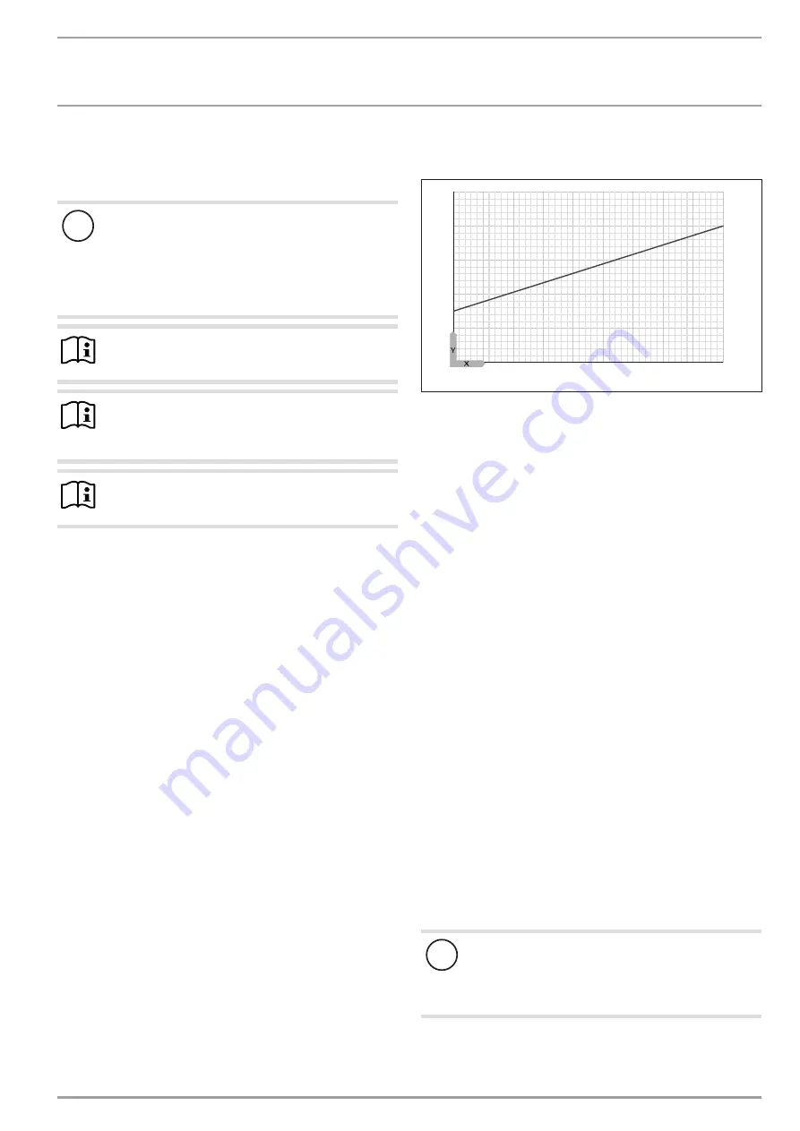
Maximum temperature differential on the heating side with buffer
cylinder:
1
0
2
4
6
8
10
-15 -10
-5
0
5
10
15
20
25
30
D
00000
63
55
0
1 Nominal flow rate
X Outside temperature [°C]
Y Maximum temperature differential [K]
f
Make the settings at the circulation pump when the temper-
ature differential between the flow and return temperature
has stabilised.
f
Compare the resulting temperature differential between the
flow and return at the appliance with the diagram “Maximum
temperature differential on the heating side with buffer cyl-
inder”.
f
Set the buffer charging pump so that the maximum tempera-
ture differential is achieved or undershot.
f
If the appliance will be used for DHW heating, check the set-
ting of the pump head in DHW mode.
f
If necessary, adjust the delivery head setting for the DHW
primary pump.
f
Set the buffer charging pump and the DHW primary pump to
∆p constant.
10.7 Condensate drain
A pipe for the condensate drain is fitted at the factory to the defrost
pan. The pipe terminates near the aperture on the floor plate. The
appliance is supplied with a two meter hose with elbow plug-in
fittings for draining the condensate.
f
Secure the hose supplied on the pipe of the defrost pan.
10.8 External second heat generator
For dual mode systems, always connect the heat pump into the
return of the second heat generator (e.g. oil boiler).
10.9 High limit safety cut-out for area heating
system
!
Material losses
In order to prevent excessively high flow temperatures
in the area heating system causing damage in the event
of a fault, install a high limit safety cut-out to limit the
system temperature.


