INSTALLATION
Installation
www.stiebel-eltron.com
WPL ACS classic |
13
f
f
Ensure that the heating flow and return are connected
correctly.
f
f
Provide thermal insulation in accordance with applicable
regulations.
f
f
When sizing the heating circuit, observe the internal pressure
differential (see chapter “Specification / Data table”).
10.6 Oxygen diffusion
!
Material losses
Avoid open vented heating systems and plastic pipes in
underfloor heating systems which are permeable to ox-
ygen.
In underfloor heating systems with plastic pipes that are per-
meable to oxygen and in open vented heating systems, oxygen
diffusion may lead to corrosion on the steel components of the
heating system (e.g. on the indirect coil of the DHW cylinder, on
buffer cylinders, steel heating elements or steel pipes).
f
f
In the event of oxygenation, separate the heating system be-
tween the heating circuit and the buffer cylinder.
!
Material losses
The products of corrosion (e.g. rusty sludge) can settle
in the heating system components and result in a lower
output or fault shutdowns due to reduced cross-sections.
10.7 Filling the heating system
10.7.1 Water quality
Carry out a fill water analysis before the system is filled. This
analysis may, for example, be requested from the relevant water
supply utility.
To avoid damage as a result of scaling, it may be necessary to
soften or desalinate the fill water. The fill water limits specified
in chapter "Specification / Data table" must always be observed.
f
f
Recheck these limits 8-12 weeks after commissioning, after
every refill and as part of the annual system service.
Note
f
f
Never add inhibitors or other additives (e.g. glycol)
to the fill water.
Note
With a conductivity >1000 μS/cm, desalination treatment
is recommended in order to prevent corrosion.
Note
Suitable appliances for water softening, as well as for
filling and flushing heating systems, can be obtained via
trade suppliers.
10.7.2 Filling the heating system
f
f
Fill the heating system on the heating side.
10.7.3 Venting the heating system
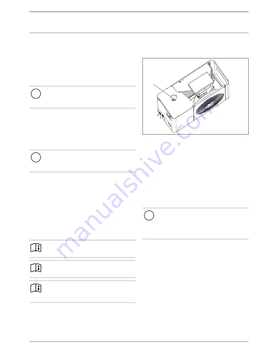
The appliance has an automatic air vent valve.
D
00000
63
48
9
1
1 Automatic air vent valve
f
f
Remove the hood and the EPS cover (see chapter "Trouble-
shooting / Checking the IWS DIP switch settings").
f
f
Vent the pipework by turning the grey cap on the automatic
air vent valve.
f
f
Close the automatic air vent valve after the venting process.
f
f
Reattach the EPS cover and hood on the appliance.
10.8 Minimum flow rate
For heating operation without a buffer cylinder, always ensure the
minimum flow rate and the availability of energy for defrosting.
10.9 Setting the flow rate on the heating side
!
Note
We recommend installing an electric emergency/booster
heater.
An emergency/booster heater is installed in some of the
products required as accessories (see chapter “Installa-
tion / Appliance description / Accessories”).
The flow rate is set automatically via the self-regulating system
(see menu “COMMISSIONING / HEATING / SPREAD CONTROL /
STANDBY PUMP RATE” in the heat pump manager).
In heat pump mode a fixed spread between the heat pump flow
and return is set (see menu “COMMISSIONING / HEATING / SPREAD
CONTROL” in the heat pump manager).
The current flow rate can be called up in the menu “INFO / HEAT
PUMP INFO / PROCESS DATA” under “WP WATER FLOW RATE”.
The appliance is designed in such a way that no buffer cylinder
is required in conjunction with appropriately sized area heating
systems.
A buffer cylinder is required on installations with several heating
circuits.


