


© 2007 Stevens AeroModel.
Page 11 of 35
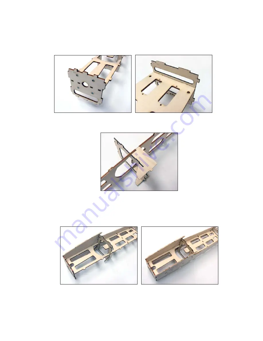
4.
Now install the former F1 to the fuselage crutch F0 observing proper forward and top-side orientation. Finally,
locate the 1/16” plywood former F3 and key to the fuselage crutch assembly as illustrated below. Again, this
formers installation direction has been identified with the scribing of “TOP” on the part to signal the top and
forward orientation of the component.
5.
Next, key the 1/16” plywood G1 landing gear supports to both sides of the fuselage crutch, as illustrated in the
photo below.
6.
Test fit the completed fuselage crutch to one of the 1/8” balsa FS fuselage sides. Any failure to follow the
proper top-side part orientation will be revealed here. If the tabs in your fuselage crutch do not align with the
notches in the fuselage side you will need to re-visit the crutch assembly and pay careful attention to the top-
side part orientation (
as instructed, you haven’t glued the crutch right?
). With the test fit successful, tack glue
each of the crutch parts together. Finally, tack glue both 1/8” balsa fuselage sides to the crutch at tab and notch
locations as illustrated below.


