background image

Document #OPM/1300, Revision B


CONFIDENTIAL 

© 2013 Copyright VTS Medical Systems, LLC


1 of 29 


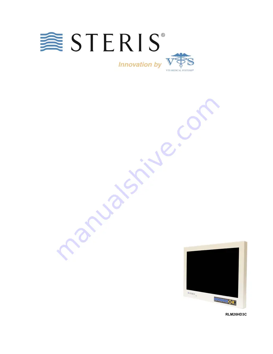
HD3 26

 Monitor


LCD Surgical Grade Monitor 
High Definition Wide Screen 


OPERATION MANUAL 

 
RLM26HD3NPWR HD3 

26

 Monitor with fiber input 

 
RLM26HD3C  

HD3 26

 Monitor with fiber input and power 

supply 

 
RLM26HD3MCNPWR HD3 

26

 Monitor with fiber input and integrated 

microphone 

 
RLM26HD3MC  

HD3 26

 Monitor with fiber input, integrated microphone, 

and power supply 


RLM26HD3C 

Summary of Contents for RLM26HD3C

Page 1: ...e Monitor High Definition Wide Screen OPERATION MANUAL RLM26HD3NPWR HD3 26 Monitor with fiber input RLM26HD3C HD3 26 Monitor with fiber input and power supply RLM26HD3MCNPWR HD3 26 Monitor with fiber input and integrated microphone RLM26HD3MC HD3 26 Monitor with fiber input integrated microphone and power supply RLM26HD3C ...

Page 2: ...rence that may cause undesired operation This device has been evaluated to the UL 60601 1 standard Equipment evaluated to this standard is not suitable for use in the presence of a flammable anesthetic mixture with air or with oxygen or nitrous oxide unless additional tests have been passed Therefore this device is not suitable for use in the presence of a flammable anesthetic mixture with air or ...

Page 3: ...rs RLM26HD3C and RLM26HD3MC include a power supply model WSX624M manufactured by Jerome Industries Corporation The European Authorized Representative AR for this product on behalf of the manufacturer is Emergo Europe Molenstraat 15 513 BH The Hague Netherlands 31 70 345 8570 Tel 31 70 346 7299 Fax service emergogroup com The CE marking certifies that this product has met European Union consumer sa...

Page 4: ...monitor 6 Step 3 Attaching the monitor to a boom arm and connecting video and power sources 6 USER INTERFACE 8 User Interface Buttons 8 Power Control 8 Video Source 8 Keypad Lock 8 OSD Menu 8 OSD ON SCREEN DISPLAY 10 OSD Navigation 10 Picture Menu 11 Layout Menu 13 Tune Menu 16 COLOR CALIBRATION PROCEDURE 20 System Menu 18 Default Settings 22 MONITOR CARE TROUBLESHOOTING 23 SPECIFICATIONS 24 GLOSS...

Page 5: ...e monitor in a suitable environment See Operating Temperature and Storage Temperature on the Specifications page of this manual Even though the monitor is classified as surgical medical grade use caution around liquids as you would with any electrical appliance Do not insert objects into the monitor Do not place the monitor on unstable surfaces In all cases refer to the specifications in this manu...

Page 6: ... four screws for mounts with thicker mounting plates The mount is sold separately Note to users attaching the HD3 Monitor to an Operating Room Equipment Management System and or Equipment Boom If the HD3 Monitor is to be mounted on a boom and or Equipment Management System the boom vendor should have wired the appropriate cables through the boom arm Step 3 Attaching the monitor to a boom arm and c...

Page 7: ...Document OPM 1300 Revision B CONFIDENTIAL 2013 Copyright VTS Medical Systems LLC 7 of 29 Figure 1 Rear view shown with and without cable cover Figure 2 Close up of ports VESA Mounting Holes with Screws ...

Page 8: ... Locking and unlocking the keypad is performed with Hot Keys as described below OSD Menu Pressing the MENU EXIT button on the user interface displays the first in a series of menus To move to the desired submenus that are available for each menu function press either the or button If in a submenu MENU EXIT will return the previous menu To exit the OSD menu select MENU EXIT The monitor s firmware v...

Page 9: ...ed Source Selection PIP source To select a PIP source the PIP selection on the Layout menu must be set to ON To select PIP ON press ENTER or open the OSD menu and navigate to the Layout page Press ENTER simultaneously then press to select the PIP source There is an option to show All sources or Active sources If Active sources is selected the Active sources sources that are connected and powered o...

Page 10: ...se Frequency Black Stretch White Stretch Transparency OSD Timeout OSD H Position OSD V Position YUV RGB Normal Full Screen Zoom In 5 4 Stretch On Off On Off H Offset V Offset Black Level Offset OSD Navigation Custom Aspect PIP Adjustments PIP Size H Position V Position EQ Enable On Off Xray Enable On Off Gamma 1 8 2 0 2 2 Serial Baud Rate 9600 19200 115200 Preset Configurations Fixed Preset 1 3 Us...

Page 11: ...hange with it After adjustment the new contrast value is displayed on the screen until Menu Exit is pressed or the OSD timeout period expires Contrast can be accessed through the OSD menus as shown above or with the hot keys or When either of the hotkeys is pressed the monitor displays the contrast adjustment menu Phase Applicable to Analog RGB and VGA signals only Phase adjusts the internal clock...

Page 12: ...default is 6500K Black Level Offset The monitor automatically detects whether the input device connected requires a black level offset The black level Offset control provides a manual override of the automatic setting There are two selections Auto and 7 5 IRE The default is Auto Black Stretch The black stretch setting enhances dark colors in light images Figure 7 Picture Menu Tint White Stretch Se...

Page 13: ...15 for information on using the setting Full Screen Scales the image to the size of the panel without preserving the aspect ratio 5 4 Stretch Used with 1080i signals centers a 5 4 aspect ratio image on the screen and stretches the image to fill the screen without cropping Custom Aspect A user defined aspect ratio will be saved under Custom Aspect when horizontal and vertical offsets are changed in...

Page 14: ...indow to be set to varying levels of transparency The default is 0 Side by side Displays the main image and PIP window side by side and scaled to the vertical size of the panel The unused areas of the panel are displayed in black PIP Source Selection Press and Enter simultaneously then press to select the PIP source PIP has to be ON to select a PIP source to turn PIP ON choose Layout then PIP in t...

Page 15: ...t is negative 100 to positive 100 in increments of five The default is 0 Color Red Green Blue Gain Increasing the gain of a color multiplies the proportion of that color by a factor Red Green and Blue can be adjusted separately Red Gain Green Gain and Blue Gain all have a default of 50 Red Green Blue Offset Increasing the offset of a color increases the proportion of that color in the background o...

Page 16: ...ncy The transparency setting enables the OSD to be set to varying levels of transparency The default is 50 OSD Time out The OSD time out setting enables the user to control the time that the OSD menu displays The OSD time out can be set from 1 to 60 seconds The default is 20 seconds OSD H Position Controls the horizontal left right positioning of the OSD menu on the screen OSD V Position Controls ...

Page 17: ...Setting DVI Video Color Space Applicable to DVI signals only There are two options available for this setting YUV is used for video timing and RGB is used for VESA PC timing RGB is the default Noise Reduction Applicable to Analog RGB and VGA signals only the noise reduction function utilizes a per pixel motion adaptive algorithm to remove noise distortion from the image while leaving the image s c...

Page 18: ...tings to the factory defaults When Factory Reset is selected the message Press Enter To Confirm will appear Press Enter to confirm reset Factory defaults are listed on page 14 Open Preset Menu Opens the preset menu shown below Figure 15 Preset Configurations Menu To select a User or Fixed Preset use the and arrow keys to navigate the presets The monitor previews with the preset values as the selec...

Page 19: ...l lines on the image Xray Enable Xray Enable can be set to On or Off The default is Off When On the backlight of the panel is set to maximum brightness for viewing films Gamma A pre configured gamma curve can be selected There are six available 1 0 1 2 1 6 1 8 2 0 and 2 2 The default is 1 6 Serial Baud Rate The serial baud rate is the rate at which information is transferred It is measured in bits...

Page 20: ...deo generator make the following selections Proper settings are required for the calibration to be saved Signal type VESA Mac RGB Format 1024x768_60Hz Pattern Staircase with 16 bars as shown below Figure 16 Staircase Test Pattern 3 On the monitor press MENU to open the OSD menu 4 Navigate to the System menu and select Analog RGB Calibration The monitor calibrates 5 Before cycling power to the moni...

Page 21: ...rn shown below Figure 17 SMPTE Bar Pattern 3 On the monitor press MENU to open the OSD menu 4 Navigate to the System menu and select YPbPr Calibration The monitor calibrates 5 Before cycling power to the monitor note how the pattern looks with calibration In the next step you will compare the image as it looks now immediately following calibration to how it looks after power is cycled 6 Reset powe...

Page 22: ...Green Gain 50 Tint 50 Blue Gain 50 Color Temperature 6500K Red Offset 50 Black Level Offset Auto Green Offset 50 Black Stretch 50 Blue Offset 50 White Stretch 50 Language English Digital Brightness 50 OSD Setting Picture Format Full Screen Transparency 50 H Position 0 OSD Timeout 20 V Position 0 OSD H Position 50 Freeze Frame Off OSD V Position 50 PIP Off RGB Video Color Space RGB PIP Adjustments ...

Page 23: ... power plug from the AC outlet if applicable and accessible Store in its original carton if available Store in a dry location in temperatures between 4 and 140 degrees Fahrenheit as listed on the Specifications page of this manual Troubleshooting Please follow these troubleshooting tips prior to contacting Customer Support The image is not displayed on the screen Are the power cord and external po...

Page 24: ...ut for embedded audio Resolution Aspect Ratio 1920 x 1200 16 10 Brightness Contrast 350 cd m2 1500 to 1 Active Screen Size Diagonal 26 inches Viewing Angle Horizontal Vertical 176 Patient Vicinity Safe Integrated Microphone RLM26HD3MC RLM26HD3MCNPWR Dimensions in mm Width Height Depth 24 7 627 17 7 450 3 5 89 Weight lb kg 20 9 Active Matrix LCD Operating Temperature 32 to 104 Fahrenheit 0 to 40 Ce...

Page 25: ...a an adjustment may be required The symptom of a frequency adjustment problem is the appearance of vertical bands in the image Adjustment to the frequency setting will help eliminate these artifacts Gain Red Green Blue Increases in the gain of a color multiplies the proportion of that color in the image by a factor The actual amount of additional color is relative to the original level of that col...

Page 26: ...ra a phase adjustment may be required The symptom of phase problems is the appearance of horizontal lines flickering through the image Sharpness This control allows vertical edges of displayed objects to be sharpened and compensates for a picture or camera with a lack of video bandwidth If the picture appears blurry on vertical edges of objects then the Sharpness control can help improve the pictu...

Page 27: ...Document OPM 1300 Revision B CONFIDENTIAL 2013 Copyright VTS Medical Systems LLC 27 of 29 Cable Pin Outs Pin Description Tip Ring Shield Gnd Table 4 Microphone Cable Mini Jack Connector Pin Outs ...

Page 28: ...eset 21 Freeze Frame 13 23 Full Screen 13 23 G Gamma 22 23 Glossary 26 I Interface 8 24 K Keypad Lock 8 9 L Language 16 23 Layout Menu 13 M Microphone Cable 28 Monitor Care 24 Mounting 5 6 N Noise Reduction 17 23 26 Normal 13 O On Screen Display 10 OSD Menu 8 OSD Navigation 10 OSD Setting 23 P Picture Format 13 15 23 PIP 9 13 14 23 Power 5 8 9 Precautions 5 Preset 21 R Reset Calibration 21 RGB Cal...

Page 29: ...M 1300 Revision B CONFIDENTIAL 2013 Copyright VTS Medical Systems LLC 29 of 29 Contact Customer Support Coverage is a registered trademark of STERIS Corporation 40 Melville Park Road Melville NY 11747 877 887 1788 ...

Reviews: