background image

Wireless Display Tester   

BL-526-106 

User Manual 


Launched in Jun.2018,revised in Jun.2018 


Copyright © 2018 STEREN .All rights reserved 


1.Introduction 

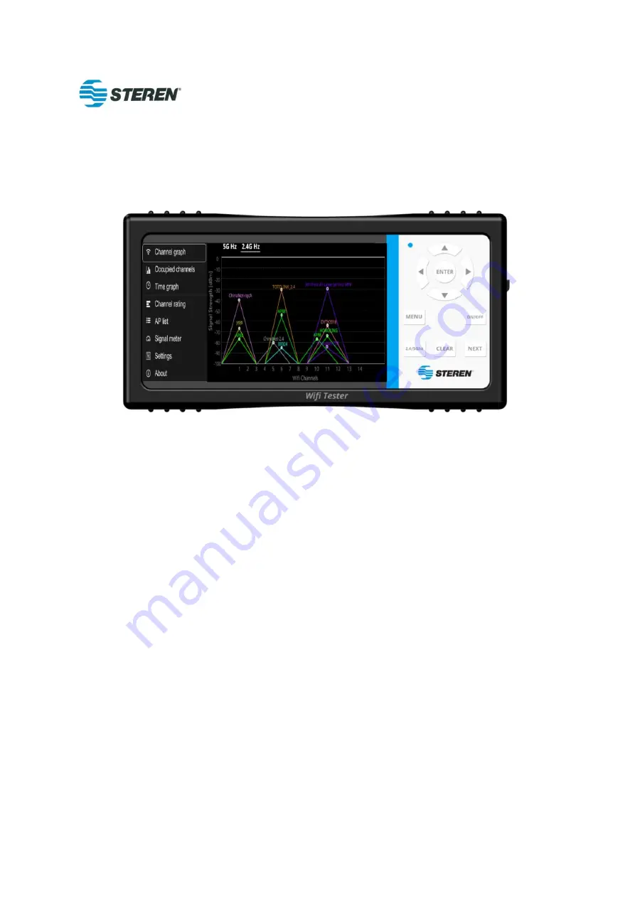
Wireless Display Tester is a portable tool that helps users find the best Wi-Fi channel and probe 
interference levels (noise floor) in the installation and troubleshooting of network fault areas to 
help  with  installation  troubleshooting,  analysis  and  testing  of  residential  and  Small  and 
medium-sized business (SMB) Wi-Fi network. This rugged handheld device is designed to operate 
in stand-alone mode and does not require connection to an access point (AP) and the installer to 
easily identify the best signal strength of the Wi-Fi device. This will help the installer decide which 
channel to use, detect strong/weak Wi-Fi signals, and determine the level of interference in the 
area. Another application is to identify the location of the "Signal Enhancer" and the Grid Add-on. 


The  Wireless  Display  Tester  operates  on  802.11b/g/n  networks  in  the  2.4  GHz  band  and 
802.11a/n/ac networks in the 5 GHz band. 
 
The product will be designed as a simplified, handheld 

"

qualified/failed

"

 device and standardized 

test instrument for use by Level 1 / field technicians. It provides technicians with a less complex 
graphical  representation  of  the  home  or  SMB  radio  frequency  (RF)  environment  with  key 
parameters for successful Wi-Fi network installations on the 2.4 GHz and 5 GHz ISM spectrum. 


Using  color-coded 

"

PASS  (green)

"

  and  "failed"  (red)  bands  (scopes  that  can  be  defined  by 

corporate policies) will show the channels available to the technician and the level of interference 

Summary of Contents for BL-526-106

Page 1: ...the installer decide which channel to use detect strong weak Wi Fi signals and determine the level of interference in the area Another application is to identify the location of the Signal Enhancer a...

Page 2: ...charging The core features and shell are unique to the market that provides cost effectiveness and you can make a fast decisions and diagnoses through failure showing When combined with an external sc...

Page 3: ...key for move right the cursor The ENTER key be sure the selected item The ON OFF key be power on or power off the device The MENU key be showing the function of menu The 2 4 5Ghz key to switch the Wi...

Page 4: ...2 Standby mode Short press the ON OFF button and the screen goes out 3 Wake up Short press the ON OFF button the screen lights up 4 Power off Long press ON OFF button for 3s the screen goes out 5 Intr...

Page 5: ...er up screen 5 2 Interface of menu Operation instructions Click Menu to pop up the side slip menu press again to hide press Up and Down to select the target function press Enter to confirm Interface o...

Page 6: ...other with the exception of channel 14 being 12 MHz apart The horizontal axis of the channel map represents 14 channels of the 2 4 GHz bandwidth and the vertical axis represents the signal strength va...

Page 7: ...or 80MHz wide Operating Instruction a Under 5G channel graph interface CH36 CH64 CH100 CH144 CH149 CH165 channels can be switched by pressing the button Up Down or Next b The left and right movement o...

Page 8: ...5GHz Bandwidth channel graph CH100 CH144 channel 5GHzBandwidth channel graph CH149 CH165 channel 5 4 Channel occupancy interface...

Page 9: ...ccupied channels b 2 4Ghz Channel occupancy of 2 4GHz and 5GHz can be switched by pressing the 2 4 5Ghz button c The left and right movement of the chart of the channel occupancy can be viewed by pres...

Page 10: ...eck the occupancy of each channel c By pressing the buttons Up Down and Next to check CH36 CH64 CH100 CH144 CH149 CH165 occupancy d The chart of the occupied channel can be moved left or right by pres...

Page 11: ...5GHz Bandwidth Channel Occupancy CH100 CH144 Channel 5GHz Bandwidth Channel Occupancy CH149 CH165 Channel 5 4 Interface of Time Graph...

Page 12: ...ess Menu button to pop up the menu list and select the Time Graph b Time graph for 2 4GHZ 5GHZ can be checked by switching 2 4 5Ghz button c Time graph can be checked by moving around Right Left butto...

Page 13: ...the better quality Green indicates the best channel quality Yellow means general red means poor channel quality Operating Instruction a Press Menu button to pop up the menu list and select Channel ra...

Page 14: ...2 4GHZ Bandwidth Channel Rating 5GHZ bandwidth Channel Rating 5 7 Interface of AP List Function...

Page 15: ...ength Yellow means Fair Red means Poor Operating Instruction a Press Menu button then in the menu list on left side of the screen to select AP List b For scanned AP press UP Down and Nex to view the a...

Page 16: ...menu list and select Signal Meter b For scanned AP press UP Down and Next to view the access points on the list c Press Enter to run or pause AP list function d Press Left to lower volume Press Right...

Page 17: ...5 9 1 5 9 2 Need add one signal range setting UI here Function...

Page 18: ...instructions refer to photo 5 9 2 f Select Brightness to pop up the brightness adjustment messagebox press Left Right to adjust the brightness then press OK or Clear to exit refer to photo 5 9 3 g Sel...

Page 19: ......

Page 20: ...that interference will not occur in particular installation If this equipment does cause harmful interference to radio or television reception which can be determined by turning the equipment off and...

Reviews: