background image


65

Sensing the Environment

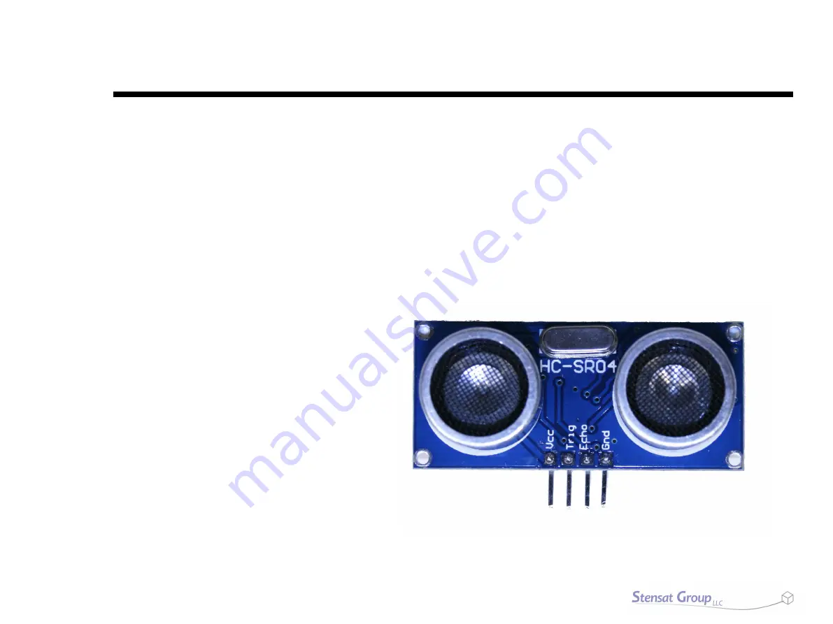
To detect things in the environment for purpose of collision avoidance, an 

ultrasonic range sensor will be added to the robot.

This sensor sends out a burst of audio signal at 40 Khz and detects the 

echo.

The processor needs to measure the time it takes for the echo to return.

This sensor has four pins

Ground

5 Volt power input

Trigger

Echo

Summary of Contents for Sten-Bot Robot Kit

Page 1: ...Sten Bot Robot Kit Stensat Group LLC Copyright 2013 ...

Page 2: ...ndoff threads breaking wires off the motors causing shorts to damage components powering the motor driver backwards plugging the power input into an AC outlet applying more than 12 volts to the power input dropping the kit kicking the kit throwing the kit in fits of rage unforseen damage caused by the user owner or any other method of destruction If you do cause damage we can sell you replacement ...

Page 3: ...3 Program Overview Assemble Kit Motor assembly Base plate assembly Electronics plate assembly Programming Calibration Running the Maze ...

Page 4: ...ffs 4 1 5 standoffs 4 right angle brackets 1 metal base plate 2 motor plates 2 geared motors 2 wheels 1 castor 1 battery holder 1 processor board 1 solderless bread board 10 jumpers 1 ultrasonic range sensor 1 LED 1 270 ohm resistor 1 Photoresistor 1 4 7K ohm resistor 1 micro switch plus hardware 1 USB cable 1 CD ...

Page 5: ...5 Tools Needed Philips screw driver 1 4 inch nut driver Jeweler blade screw driver ...

Page 6: ...trol the direction and operation of each motor A control signal causes the ultrasonic range sensor to send out a ping A signal goes back to the processor when the echo is detected The processor times how long it takes to receive the echo to figure out distance Battery Battery Processor Board Processor Board Motor Controller Motor Controller Left Motor Left Motor Right Motor Right Motor Ultra Sonic...

Page 7: ...er needs to be assembled Notice that one side of the motor has a circular plastic shape sticking out Insert inch screw as shown and secure the inch standoff Tighten with the screw Make sure the orientation is as in the picture The standoff threads need to point away from the motor 1 4 inch ...

Page 8: ...1 inch long screws Secure the top screw with a nut For the bottom screw install a right angle bracket Use the larger hole that is not threaded Secure with a nut Secure the standoff with a nut Install a second bracket with a inch screw and nut Use the hole that is not threaded 1 inch screws 1 4 inch screw ...

Page 9: ...9 Motor Assembly Assemble the second motor in the mirror image of the first The two motors should look like below 4 40 4 40 1 x 2 1 x 2 standoffs ...

Page 10: ...ors Align the brackets to the holes shown in the picture Secure with two 3 16 inch screws from the bottom side You may need to loosen the screws on the motor mount brackets to align the brackets Re tighten all screws 3 16 ...

Page 11: ...11 Robot Plate Assembly With the motors installed mount the caster at the rear using the two holes and the screws from the caster parts Secure the caster holder with the two screws and nuts ...

Page 12: ...mounted in the marked rectangular area Use the 1 2 inch screws and nuts to secure as shown in the next page Insert the screws from the top through the solderless bread board and secure with nuts on the back side Make sure the solderless bread board is oriented as shown in the picture on the next page Solderless Bread Board Holes ...

Page 13: ...13 Processor Board Mount The process board is mounted differently Insert screws from the back side and install a nut on each screw The nuts will serve as standoffs for the processor board ...

Page 14: ...14 Electronics Base Plate Assembly Place the processor board on top of the nuts Insert another set of four nuts to secure the processor board ...

Page 15: ...15 Mounting Electronics Plate Install four 1 5 inch long standoffs with the threaded end inserted into the plate Secure with nuts from the bottom side of the plate 1 5 inch Standoffs 1 5 inch Standoffs ...

Page 16: ...16 Mounting the Electronics Plate Secure the electronics plate on top of the standoffs using 4 40 1 4 inch screws inch Screws inch Screws ...

Page 17: ... double sided tape and stick them to the underside of the battery holder Peel the other side and stick it to the base plate as shown Using a small blade screw driver secure the battery holder wires to the processor board Red wire to Side Closest to switch Black wire to right of Red ...

Page 18: ...18 Installing the Wheels The wheels are installed by pressing them onto the geared motor shaft The shaft is keyed Press fit the wheel onto the shaft ...

Page 19: ... memory 1KB Ram 512 Byte EEPROM 6 Digital IO ports Can be configured as input output Servo PWM 6 Analog ports 0 5 volt range I2C Interface Built in pull up resistors Supports 100 KHz and 400 KHz speeds UART Interface Up to 57600 baud Shared with USB port USB and External power up to 12 V 500 ma max current ...

Page 20: ...pin has 5V and GND in a row Allows servos to be connected directly 500ma total for all digital ports Digital 5V requires external power source Separated from USB power to protect PC Analog Pins 0 1 2 3 6 7 available 5V always available 0 to 5 volt input range Higher voltages will cause damage Digital Pins Analog Pins ...

Page 21: ...and always powered I2C 2 2 Kohm pull up resistors included 5V and ground included and always powered External power Up to 12 volts allowed Supplies power to digital port 5V pins Up to 500ma Reverse voltage protection Over current protection Thermal overload protection Terminal block provided to allow flexibility in power source connection Power selection Move shorting block between USB and EXT Pow...

Page 22: ...USB Port Used for programming and UART interfacing with USB host PC Power source selection Jumper to select between USB power and external power Set jumper to USB for power from PC Power switch is not active Digital ports do not have 5V unless external power is selected Set jumper to EXT for external power Power switch is active Digital ports have 5V ...

Page 23: ...lect Arduino Pro or Pro Mini 3 3V 8MHz with ATMega168 Plug Processor board into the computer USB port Let the operating system find the drivers network connection required Driver is also included with arduino software In the arduino program select menu Tools Select serial Port Select the appropriate COM port Sometimes you need to guess the port Usually not COM3 which is usually the modem port ...

Page 24: ...t has a text editor and compiler It uploads programs to the processor board It has a serial monitor for displaying any text sent from the arduino Verify Code Upload Code New Program Open Save Serial Monitor Area for entering code error message area ...

Page 25: ...ters Plug the processor board into the USB port Click on the upload Code button to compile and upload the program When the status message at the bottom of the window says done uploading click on the serial monitor button A window pops up with the message being displayed Experiment by changing the message void setup Serial begin 9600 void loop Serial println Hello World Serial Monitor Window ...

Page 26: ...e loop This program configures the serial interface to send messages at 9600 bits per second The message is Hello World and is repeatedly displayed void setup Serial begin 9600 void loop Serial println Hello World delay 500 Serial begin is a function that intializes the serial interface and sets the bit rate Serial println sends the specified message over the serial interface and move the cursor t...

Page 27: ...nected Each row of holes that go left to right on the top and bottom are all connected together The columns of 5 holes are all connected together The lines in the picture show the connections Components and wires are inserted in the holes to make connections Back side showing how holes are connected ...

Page 28: ...he LED is a polarized device and only works in one direction The positive pin on the LED is the longer pin LEDs need the current to be limited Include a supplied 270 ohm resistor in series with the LED when connecting ...

Page 29: ...e right The symbol at label R1 is for the resistor LED1 is next to the symbol for the LED The symbol at the top is the 5V connection It is called VCC The GND symbol is for ground This is the zero volt reference The LED has an anode and a cathode The anode is the long pin When the anode is at a higher voltage than the cathode the LED will light Anode Cathode Resistor 5V ...

Page 30: ...30 Wiring Diagram for LED LED Resistor Long lead ...

Page 31: ...function controls a pin and can set it high or low When set high the pin is set to 5 volts When set low the pin is set to 0 volts The function is written as digitalWrite pin setting setting is HIGH or LOW The letters need to be capital ...

Page 32: ...to the right will cause the LED to blink In the setup function digital pin 3 is configured as an output in the loop function digital pin 3 is set high which causes the pin to generate 5 volts The delay function halts the program for 500 milliseconds The next digitalwrite command sets digital pin 3 to 0 volts turning off the LED void setup pinMode 3 OUTPUT void loop digitalWrite 3 HIGH delay 500 di...

Page 33: ...33 LED Connected to Port 3 Digital Pin D3 ...

Page 34: ...he photo resistor will have a resistance ranging from 1 Mohm in darkness to 100 ohms in bright light Install the photo cell and 4 7 K resistor on the solderless bread board Make sure the photo cell and resistor are connected Connect the free end of the resistor to GND at the analog connector Connect the free end of the photo cell to 5 volts Connect the resistor and photo cell connection to pin 0 o...

Page 35: ... location Once the ADC value is read it can be converted to a voltage value The code to the right shows the equation which can be used for all the analog ports The Serial println function that displays the volts includes a numeric argument which specifies the number of decimal places void setup Serial begin 9600 void loop int a float volts a analogRead 0 Serial println a volts float a 1023 0 5 0 S...

Page 36: ...r Control Dual H Bridge Driver is used to control the motors It uses four transistors to control the polarity of the voltage supplied to the motor Below shows the H bridge driver circuit and the current flows ...

Page 37: ...ection of the motors and turn them on and off The following pages will describe how to hook up the motors A motor driver module is needed This module allows a computer to control the motors The motors require more power than the computer signals can provide so the module provides the power The motor driver uses what is called an H Bridge Driver ...

Page 38: ...sed to control the motors It uses four transistors to control the polarity of the voltage supplied to the motor The transistors are used as switches turning on and off Below shows the H bridge driver circuit and the current flows Motor Battery ...

Page 39: ...e direction two switches need to be turned on to let power get to the motor One switch connects the positive side of the battery to to one side of the motor and another switch connects the negative side to the other side of the motor Motor Battery ...

Page 40: ...40 Motor Control Flip all the switches to the opposite position and the motor turns in reverse Notice the polarity signs on the motor switched sides Motor Battery ...

Page 41: ...e is shown at the top right The square block in the center contains the two motor drivers The bottom picture shows the signal names next to the pins Power is supplied at pins GND and VIN Control signals for each motor is A1 IN A2 IN and B1 IN B2 IN The motors connect to the pins marked OUT The other pins are not used ...

Page 42: ...wing shows how the H Bridge driver works Only one is shown There are two signals that control the direction and operation Control logic decodes the two signals and turns on the appropriate switches to control the motor The drawing shows the condition of AIN1 and AIN2 set to logic zero ...

Page 43: ...Driver Works Control Logic Motor Battery AIN1 1 AIN2 0 When AIN1 is set to logic 1 the motor drives in the forward direction You will notice that setting AIN1 1 and AIN2 0 turns on two signals that turn on the two switches ...

Page 44: ...Driver Works Control Logic Motor Battery AIN1 0 AIN2 1 When AIN1 is set to logic 1 the motor drives in the forward direction You will notice that setting AIN1 1 and AIN2 0 turns on two signals that turn on the two switches ...

Page 45: ...th AIN1 and AIN2 to logic 1 you get a breaking action This turns on the two bottom switches which shorts the motor connections together The inductance created by the motor turning in one direction will power the motor to turn in the opposite direction It causes the motor to slow down quickly ...

Page 46: ...46 Mount the Motor Controller Insert the motor controller module into the solderless breadboard as shown The rows of pins need to on either side of the gap down the center of the board ...

Page 47: ... from GND on the motor controller to GND at Signal D6 on the processor board Connect a wire from VCC on the motor controller to 5V on the processor board Connect A1 IN to D11 Connect A2 IN to D10 Connect B1 IN to D9 Connect B2 IN to D6 This completes the connections between the motor controller and the processor board ...

Page 48: ...48 Motor Controller Wiring Diagram ...

Page 49: ...9 Wiring the Motors Now connect the motors Connect the left motor wires to OUT B1 and B2 Connect the right motor wires to OUT A1 and A2 Don t worry if they are wired backwards That will be corrected next ...

Page 50: ...50 Wiring Diagram for Motors Left Motor Right Motor ...

Page 51: ...osite direction The same applies for B1 and B2 Enter the program on the right to turn the motors on See which way they are turning and swap the motor pins if needed to make the motors spin forward These pin settings will be used for forward motion void setup pinMode 6 OUTPUT pinMode 9 OUTPUT pinMode 10 OUTPUT pinMode 11 OUTPUT void loop digitalWrite 6 HIGH digitalWrite 9 LOW digitalWrite 10 HIGH d...

Page 52: ...e digital pins D10 and D11 control the right motor Setting D10 high and D11 low makes the left wheel spin forward Setting D10 low and D11 high makes the left wheel spin reverse Setting D10 low and D11 low turns off the motor Making the left motor go forward and the right motor go reverse turns the robot right Making the left motor go reverse and the right motor go forward turns the robot left The ...

Page 53: ...italWrite 6 LOW digitalWrite 9 HIGH digitalWrite 10 LOW digitalWrite 11 HIGH Stop digitalWrite 6 LOW digitalWrite 9 LOW digitalWrite 10 LOW digitalWrite 11 LOW Right Turn digitalWrite 6 LOW digitalWrite 9 HIGH digitalWrite 10 HIGH digitalWrite 11 LOW Left Turn digitalWrite 6 HIGH digitalWrite 9 LOW digitalWrite 10 LOW digitalWrite 11 HIGH ...

Page 54: ...54 Driving Around Once motor wiring has been set modify the program to drive around Add to the program to turn and reverse Include a delay between setting the directions to give the robot time to move ...
Page 55: ... controlling their speed A simple way to control the speed is to pulse power to the motors This technique is called pulse width modulation On the arduino the analogWrite function performs this It generates a repeating pulse at about 250 Hz The size of each pulse is the duty cycle The higher the duty cycle the more power the motor gets Adjusting the duty cycle will adjust the motor speed ...

Page 56: ...nalogWrite function takes two values First is the pin number Second is the duty cycle represented as a value from 0 to 255 0 is 0 duty cycle 255 is 100 duty cycle 127 is 50 duty cycle The function is written as analogWrite pin duty ...

Page 57: ... all the time This is the same as digitalWrite function Run the code and see which direction the robot drifts Reduce the value for the opposite direction by 10 and try again Keep adjusting until the robot drives relatively straight It won t be perfect void setup pinMode 6 OUTPUT pinMode 9 OUTPUT pinMode 10 OUTPUT pinMode 11 OUTPUT void loop analogWrite 6 255 analogWrite 9 0 analogWrite 10 255 anal...

Page 58: ... distance and the amount of turning Mark off two feet on the floor Floor tile is usually 1 foot square Write a program to move forward two feet and stop Start with a delay of 1000 ms Adjust the delay until the robot travels two feet Keep this value If necessary adjust the PWM values to keep the robot as straight as possible 2 Feet Start Stop ...

Page 59: ... for your right angle Program the robot to turn right and set the delay to 400 ms and turn off Place the robot on the corner of the right angle facing the left line See how much the robot turns and adjust the delay until it turns 90 degrees Verify the value turning left and adjust if necessary Floor Tile ...

Page 60: ... switch to the right is to be mounted to the base of the robot kit The micro switch comes with two 5 8 long screws and nuts Position the micro switch as shown to the right and insert the screws from the bottom Secure each screw with a not on the top side Tighten until snug but do not over tighten as that may damage the switch ...

Page 61: ...the bottoms side of the base plate The micro switch is installed at an angle Take two jumper wires and insert them into the micro switch Connect one jumper wire to GND near digital signal D3 of the processor board Connect the other wire to digital signal D3 GND D3 ...

Page 62: ...ut with internal pull up resistor activated That means when nothing is connected D3 will indicate a value 1 high signal When the micro switch is pressed the internal contact is closed which connected GND to D3 The program will indicate a value 0 low signal void setup Serial begin 9600 pinMode 3 INPUT_PULLUP void loop int a a digitalRead 3 Serial println a delay 200 ...

Page 63: ...talWrite 6 HIGH go forward digitalWrite 10 HIGH a digitalRead 3 check contact if a 0 digitalWrite 6 LOW stop digitalWrite 10 LOW digitalWrite 9 HIGH go reverse digitalWrite 11 HIGH delay 500 digitalWRite 11 LOW turn delay 400 digitalWrite 9 LOW stop void setup Serial begin 9600 pinMode 3 INPUT_PULLUP pinMode 6 OUTPUT pinMode 9 OUTPUT pinMode 10 OUTPUT pinMode 11 OUTPUT ...

Page 64: ...lay 400 digitalWrite 9 LOW The first part of the loop has the robot moving forward The micro switch is checked to see if it closed If the micro switch is closed variable a is zero This causes this block of code to be executed This code makes the robot stop This code makes the robot go reverse This code makes the robot turn right after 500ms of going reverse This code makes the robot stop after 400...

Page 65: ...ision avoidance an ultrasonic range sensor will be added to the robot This sensor sends out a burst of audio signal at 40 Khz and detects the echo The processor needs to measure the time it takes for the echo to return This sensor has four pins Ground 5 Volt power input Trigger Echo ...

Page 66: ... robot The pins are inserted at the end of the rows Connect jumpers from the sensor to the processor GND to Analog GND ECHO to pin D3 TRIG to pin D5 VCC to Analog 5V Look on the processor board for the word ANALOG The power connections are done there to isolate the sensor from the motor power to reduce electrical noise ...

Page 67: ...s an input A new command that will be used is called pulseIn This measures the time it takes a pulse to occur in microseconds Try the program to the right The results are in centimeters void setup Serial begin 9600 pinMode 3 INPUT pinMode 5 OUTPUT void loop digitalWrite 5 LOW delayMicroseconds 2 digitalWrite 5 HIGH delayMicroseconds 10 digitalWrite 5 LOW int distance pulseIn 3 HIGH distance distan...

Page 68: ...is function will return a result The return command specifies which variable is sent back to the calling code int ultrasonic digitalWrite 5 LOW delayMicroseconds 2 digitalWrite 5 HIGH delayMicroseconds 10 digitalWrite 5 LOW int distance pulseIn 3 HIGH if distance 0 return 1000 distance distance 58 return distance The function pulseIn returns the number of microseconds The result is then divided by...

Page 69: ... object The format for the if statement is shown to the right Multiple statements can be inserted between the brackets and will be executed if the condition is true To test for equals use else allows two sets of codes to be executed depending on the condition if a c execute code here if a c execute this code if a c execute this code else otherwise execute this code ...

Page 70: ...ether the program will hopefully keep the robot from bumping into anything Enter the code on the next page The code should be written in a single file The code is split on the next page since it wouldn t fit in a single column Test it and see if you need to tweak the timing for going reverse and turning Change the code to turn a different direction ...

Page 71: ... 1000 distance distance 58 return distance void setup pinMode 3 INPUT pinMode 5 OUTPUT pinMode 6 OUTPUT pinMode 9 OUTPUT pinMode 10 OUTPUT pinMode 11 OUTPUT void loop int distance digitalWrite 6 HIGH digitalWrite 10 HIGH distance ultrasonic if distance 10 digitalWrite 6 LOW digitalWrite 10 LOW digitalWrite 9 HIGH digitalWrite 11 HIGH delay 1000 digitalWrite 11 LOW delay 700 digitalWRite 9 LOW ...

Page 72: ...The large square represent 2 foot grids The red rectangles represent a barrier that can be detected with the ultrasonic range sensor Set up some barriers out of any solid material Use the ultrasonic range sensor to avoid crashing into the barriers and turns the right direction every time a barrier is detected Start Finish ...

Page 73: ...ic Sensor Specifications Operating voltage 5V 2ma current Induction angle 15 degrees Detection range 2cm 450 cm 3mm precision Trigger signal 10 us minimum high pulse Module sends a 8 cycle 40 Khz burst square wave ...

Reviews: