


16
Q
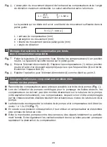
Expansion joints are to be mounted according to installation mode
, meaning, the
screw head should always be placed on the bellows side, with the nut on the piping side.
If this is not possible, the screw length is to be selected according to Installation mode
in such a way that the bellows is not damaged in the process. When using flanges with
threaded bolt holes, make sure that the screw lengths close off with the flange itself
.
The danger of damage increases with excessively long screws when the rubber bellows
expands under pressure in the operating condition
.
Q
During installation, ensure that the bores of the piping flanges are aligned. If necessary,
re-adjust the revolving flanges at the expansion joint.
Q
When the system is used for aggressive media (e.g. sea water, acids, lyes etc.) the inner
surfaces of the pipe system as well as the flange sealing surfaces must be coated with
an efficient corrosion protection coating.
Fig.
The sealing surfaces of the mating flanges must be thoroughly flat and clean.
Fig.
Tongue-and-groove flanges are NOT acceptable.
Fig.
Recesses/shoulders must be balanced out with equalising elements.
Fig.
Revolving flanges with a welding neck are not suitable. No uniform pressing effect.
Fig.
An additionally installed gasket (65 + 5 Shore A) protects the rubber sealing surface
against sharp-edged pipe ends.
Fig.
10
Sharp-edged pipe ends cut into the rubber sealing surface.
Fig.
11
With constructed rubber flanges, a full pressing effect is only possible with smooth
mating flanges.
Fig.
12
Mating flanges with projection crush the rubber flange, the press-on flange located
behind will tilt – pressing effect is inadequate.
Q
Tighten the flange screws evenly and crosswise. Use the spanner to hold the screw head
on the inside, and turn the nuts on the outside in order to avoid damage to the bellows
with the tools. After the first start-up, re-tighten the screws as required.
Q
A torsional strain (twist) of the expansion joint during installation/deinstallation and in the
operating condition is not acceptable. This applies in particular for models with threaded
connections, held by a spanner at the hex.
Q
When performing electro-welding on the pipework in the vicinity of the expansion joints,
these must be bridged over with earthing strands. In principle, the expansion joints must
be suitably protected against welding spatter and thermal negative effects during wel-
ding.
Q
With high flow velocities involving possible resonance or turbulence caused by re-rou-
ting of the flow direction (e.g., downstream of pumps, valves, T-pieces, pipe bends), a
guide sleeve (LR) must be installed. When installing, observe the flow direction (arrow
direction = flow direction).
Q
As far as possible, install expansion joints in such a way that they can be visually inspec-
ted at regular intervals for intact condition.
Q
Cover off the expansion joints to protect them against damage of all kinds.
Q
Do not apply paint or any insulation to the bellows.
Q
Wait until installation is completed before removing the pre-stress devices.
Q
The piping must be provided with adequately dimensioned fixed points to absorb the
forces of the pipe system and piping guides. The user is responsible for professional
execution in accordance with standard engineering practice.
Summary of Contents for A Series
Page 2: ...2 ꔴ A ꔴ A 9 9 9 9 10 11 12 ...
Page 3: ...3 ꔴ B ꔴ M 3 3 3 3 2 3 3 FFP F1 F2 F3 ...
Page 4: ...4 ꔴ C ꔴ D ...
Page 76: ......


