background image


f. Use the search wheel to move to the next input and repeat the naming procedure. 

g. When all necessary inputs have been named, use the Exit menu item to return to the Installation 

menu. 


No inputs will be available and displayed unless they have been named! 


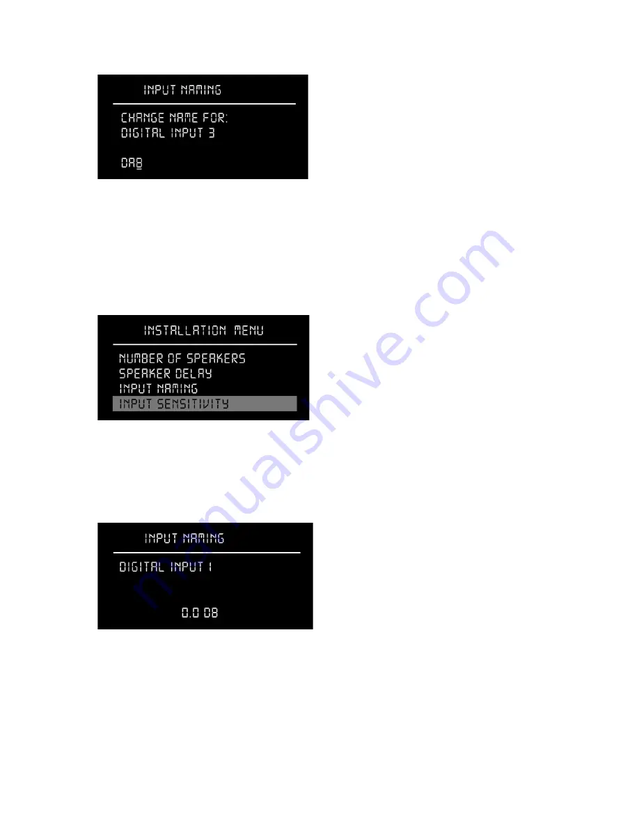
Input Sensitivity 


This setting allows you to change sensitivity for each input source, so no change in volume level can 

be heard when the customer switches between signal sources. 


a. In the sub menu, press 

ENTER

 to choose the input for which you want to change sensitivity.  


b. To adjust the sensitivity in decibel, spin the search wheel counterclockwise for decreasing and 

clockwise for increasing sensitivity. 

c. Press 

ENTER

 to store and exit each input. 

d. Repeat the procedure for each activated input. Then select the Exit menu item to return to the 

Installation menu. 


20 


Summary of Contents for C

Page 1: ...MODEL C INSTALLATION MANUAL VERSION 2 0 Skriv tekst ...

Page 2: ...CKING MODEL C MUSIC SYSTEM 6 SYSTEM PLACEMENT IN THE ROOM 9 ASSEMBLY OF MODEL C MUSIC SYSTEM 10 USER INTERFACE MODEL C MUSIC SYSTEM 16 MODEL C SOFTWARE PROGRAMMING 17 MODEL C ROOMPERFECT CALIBRATION 23 ROOMPERFECT TROUBLESHOOTING 29 RESET INTEGRATION HANDING OVER TO OWNER 31 TRADEMARKS 33 SERVICE INFORMATION 34 2 ...

Page 3: ...ials in accordance with your local recycling regulations Products and equipment which must be collected for reuse recycling and other forms of recovery are marked with the icon of the crossed out waste receptacle FCC Steinway Lyngdorf products and accessories comply with parts 15 and 68 of the FCC rules Operation is subject to the following two conditions 1 this device may not cause harmful interf...

Page 4: ... noise radiation Accessories Included In the system accessories box located in the head unit crate you will find a complete set of link cables for use between head unit speakers and boundary woofers a measurement microphone a microphone stand and cable for calibration of the RoomPerfect system For handling during installation several pairs of white gloves have been included in the accessory pack P...

Page 5: ...5 ...

Page 6: ...side the corner of the boxes as illustrated WARNING Be very careful when you unlock the clips They are firmly fixed and may cause damage when they spring open unless you keep the clips in place with your free hand as illustrated Once you have unclipped the box remove the top The speakers are bolted to two wooden plates equipped with handles and lifting points In the right channel speaker box in a ...

Page 7: ...aging is a dolly cart with four multi directional wheels It is placed as a lid above the amplifier module compartment in the right speaker crate You can use the dolly for moving the speakers into and inside of the place of installation Unlock the Clip Lok clips following the instructions on page 8 and the dolly can be taken out of the crate Unpacking the Model C Head Unit The head unit must be unp...

Page 8: ...he remote control on the supplied docking station located in the System Accessories box and connect the system to a wall outlet The Steinway lyre logo on top of the remote control will blink as long as charging is going on Depending on the remaining power level in the batteries a full charging may require 3 4 hours Charge the remote control while you install the Model C Music System The System INS...

Page 9: ...requency response in the listening position remains the same For perfect performance these recommendations must be followed The speaker must be located at least 1 meter or 3 3 feet 50 cm or 1 65 feet from the rear edge of the metal base away from rear walls The speaker must be located at least 1 5 meter or 4 8 feet away from side walls The Boundary Woofers must be located in a corner and placed in...

Page 10: ...d with ordinary carpet b 12 pieces of 48 mm high spikes for floors covered by thick carpet c 12 pieces of non penetrating feet mainly for marble granite or similar floor materials Spikes are the most stable option but might cause damage to the floor below therefore the use of spikes will be each customer s own responsibility Steinway Lyngdorf cannot take any responsibility for any damages caused b...

Page 11: ...mpartments on the speaker stands and wired prior to operation First the electronics module must be inserted into the lacquered amplifier cabinet on the speaker stand Remove the rear panel as seen above Then remove the two M6 bolts on top of the wooden cabinet Pull out the three speaker wires with plugs as shown below The metal plugs might scratch the lacquered base Be careful Be sure to lead the c...

Page 12: ...ust be connected to the amplifier module as follows 1 Midrange Tweeter Silver plug This must go into the LEFT silver plated Speakon terminal 2 Woofer minus This must go into the CENTER Speakon terminal 3 Woofer plus Black plug This goes into the RIGHT black plated Speakon terminal If the two outer connections have been reversed the speaker will not produce any bass and will sound very distorted No...

Page 13: ... RJ 45 port for output to the next speaker in line DIP Switchboard Addressing The DIP switchboard in the upper left corner of the interface board must be encoded in order to make it possible for the head unit to identify the speaker The DIP switchboard has eight switches Use only DIP 1 4 for addressing DIP switches 5 7 are not in use Uneven numbers refer to left channel speakers even numbers to ri...

Page 14: ...of balanced XLR terminals So in total five digital and four analog sources can be connected to the head unit Each input to be used must be activated by naming it in the Installation Menu Connecting the Power Cables DO NOT power up Model C before you have read the power up sequence instruction on the next page When all signal connections have been properly made you can connect the Model C to the ma...

Page 15: ... is activated Therefore the speakers must be powered up first so that the head unit immediately can track them Consequently if the head unit is powered up first there will be no active speakers to track and you will receive an error message E in the volume display In case of failure and the head unit cannot identify any speakers turn off all components and do the power up sequence again as describ...

Page 16: ...ntrol is an RF device and must be charged and installed prior to operation Voicings are six preset tone controls that can be toggled through using the dedicated button Use the search wheel and the enter button to locate and select functions in the display The menus are self explanatory Please observe that in the Installation Manual the Enter button is referred to as Select The display shows either...

Page 17: ...and release SKIP back second right button 4 Press and release SKIP forward 5 Release the INPUT button You will then gain access to the Installation Menu Remote Control Setup a Select REMOTE CONTROL SETUP in the Installation Menu b Select ADD REMOTE c On the remote control Press and hold down the Voicing Skip Left and Skip Right buttons simultaneously until the MAC address appears in the head unit ...

Page 18: ...aker Delay menu In the Speaker Delay menu distances from all speakers to the listening position can be entered making it possible to delay the sound accordingly The sound from all speakers will then arrive simultaneously at the listening position The delay time must be adjusted individually for main and woofers a Measure the distance between main and the listening position Also measure between woo...

Page 19: ...it from the Speaker Delay menu Input Naming Up to nine external signal sources can be connected five digital and four analog Every input to be used must be given a name otherwise it will not appear in the User Menu a Press ENTER for choice of entry b Spin the search wheel to search for letters and numbers c When the desired character is found press SKIP FORWARD to store the character and move the ...

Page 20: ...nsitivity for each input source so no change in volume level can be heard when the customer switches between signal sources a In the sub menu press ENTER to choose the input for which you want to change sensitivity b To adjust the sensitivity in decibel spin the search wheel counterclockwise for decreasing and clockwise for increasing sensitivity c Press ENTER to store and exit each input d Repeat...

Page 21: ...9 9 dB This setting may be changed by this procedure a Press ENTER to enter the Default Volume menu b Adjust level by spinning the Search wheel c Press ENTER to store the new setting and exit the menu Maximum Volume The maximum volume setting is 99 9 dB This can be changed to a lower level if necessary by the following procedure a Press ENTER to enter the Max Volume menu 21 ...

Page 22: ...or popular music a maximum volume setting of 92 dB is recommended in order to avoid any amplifier clipping or speaker overload For classical music where general recording levels are lower than for pop music a higher setting might be necessary For popular music a maximum volume setting of 92 dB is recommended 22 ...

Page 23: ... the room But the measurements will last longer depending on the level of background noise RoomPerfect Preparations a Place the microphone on the tripod stand Be sure to fasten the screws properly so the microphone does not move during a measurement b Plug the supplied microphone cable into the microphone c Connect the microphone cable to the XLR microphone terminal on the rear panel of the head u...

Page 24: ...wer the volume towards the desired maximum volume shown on the display but ensure you avoid clipping uncomfortably loud levels or damage to the loudspeakers Continue choosing Retry calibration for a re estimation of the desired maximum calibration volume until an appropriate calibration volume has been reached If you find the suggested calibration volume too loud then simply turn down the volume t...

Page 25: ...or the low and high frequency measuring signals are 25 and 5 seconds respectively You can exit a commenced measurement by clapping close to the microphone Do not sit in the listening position during measurement The measurement will stop prematurely if an error occurs during the process and an error message is displayed Press ENTER to continue and Retry focus measurement press Enter is displayed If...

Page 26: ...positions is necessary Press ENTER in the Menu The message Measuring first Room Position Please wait will be displayed The test signals will sound until the message RoomKnowledge XX appears and you will be told to move the microphone to the next room position Thereafter place the microphone in another position and press ENTER to start the next measurement This procedure must be repeated at least 3...

Page 27: ...rements In the next menu select YES for saving the data Calculation of Focus 1 and Global Filters The RoomPerfect system will now calculate the filters and show Calculating filters Please wait in the display Global filter is a setting where the music will sound good and uniform all over the room whereas Focus 1 optimizes the sound for the listening position Adding More Focus and Room Positions You...

Page 28: ...the room correction The RoomCorrection index is a measure of how much processing is being employed in the room correction filters To some extent the RoomCorrection index reflects how audible the correction is However the same amount of processing can sound very different due to placement in frequency of the processing For low values below 10 of the room correction index only subtle correction is n...

Page 29: ...oise levels inside or close to the room Fault Low signal This is displayed when the measurement has lasted more than 5 min for the low frequency signal or 2 min for the high frequency signal This happens most often when using a low level measuring signal compared to the background noise of your environment which results in prolonged measuring times Solution Raise the measuring signal volume before...

Page 30: ...e displayed You will be asked if you want to Retry measurement Press Enter to retry In case of errors one of the following messages will be shown in the head unit display RoomPerfect troubleshooting WARNING The microphone is a very sensitive and calibrated device Treat it with utmost care If the microphone has been dropped on the floor or otherwise maltreated it may have been damaged Contact Stein...

Page 31: ...sories Box This communicates via RF with the Model C head unit You install it like a remote control which is also working on RF a Select Add Remote in the Model C Installation Menu b Connect the supplied Remote Interface Box to for instance the Crestron system and to mains power c The MAC address of the interface box will be displayed The system will ask if you wish to add it Confirm this d If you...

Page 32: ...the Owner s Box onto a bookshelf Demonstrate the system features for the owner Demonstrate the sound for the owner Put your business card into the Owner s Manual Box for future reference Repacking of Model C Music System In case the system components are to be moved to another location requiring extensive physical handling or repacking into the shipping crates it will be necessary to wrap the spea...

Page 33: ...trademarks or registered trademarks of HDMI Licensing LLC Dolby and the double D symbol are registered trademarks of Dolby Laboratories This product incorporates technology that is protected by U S patents and other intellectual property rights Use of this technology must be authorized by Macrovision and is intended for home and other limited viewing uses only unless otherwise authorized by Macrov...

Page 34: ... Fax 45 9614 5601 In some cases the Customer Service Department may solve a service problem without the need of repair or any other measures thereby avoiding further inconvenience or delay In some cases it may be necessary to return the equipment to Steinway Lyngdorf or an authorized service provider for repair therefore it is recommended that you save your original packing materials Steinway Lyng...

Reviews: