


5
CAB
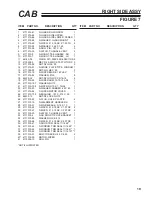
10. On the inside of the removed pump cover, install
the top filler plate
(Item 5)
using two .25 x .75
screws
(Item 27)
and two locking nuts.
(Item 23)
Install the screws from the outside inward.
Figure 7
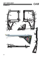
11. Install the filler dash bottom
(Item 4)
using two
.25 x .75 screws
(Item 27)
and two locking nuts
(Item 23)
. Install screws from outside in.
Figure 8
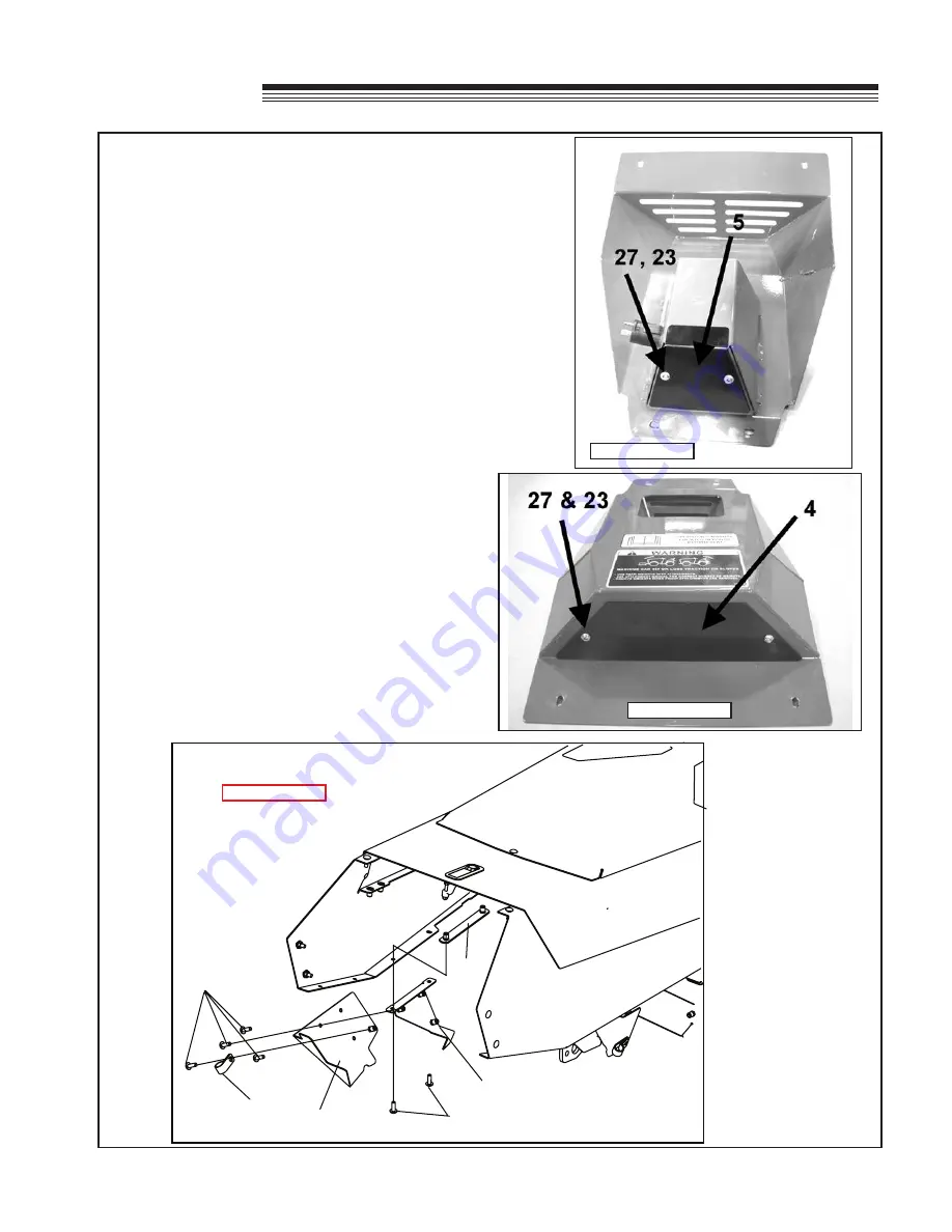
DASH FILLER PANEL INSTALLATION:
12. Open the hood and attach the LH dash filler
mount
(Item 12)
to the hood using the LH filler
dash bracket
(Item 11)
and two .25 x .75 screws
(Item 27)
. The screws will go up from the bottom
of the mount, through the hood, and screw into
the filler bracket. Tighten both screws.
Figure 9
13. Install the LH dash filler assembly
(Item 8)
to
the LH dash filler mount installed in Step 12
using three .25 x .75 screws
(Item 27)
. Tighten
screws. Install one Insulated hose clamp
(Item
21)
to the LH dash filler assy
(Item 8)
using one
.25 x .75 screw
(Item 27)
.
Figure 9
FIGURE 8
FIGURE 7
FIGURE 9
11
27
27
12
8
21
ASSEMBLY
Summary of Contents for 75-71215B4
Page 13: ...11 CAB PARTS SECTION ...


