www.autani.com
www.autani.com
8
9
Mounting
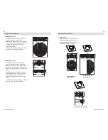
End of fixture mounting -
HBS 300, HBS 200
EM 1 Extender Module
Placement guidelines - HBS 300, HBS 200
The HBS 300 and HBS 200 typically
mount to a 1/2” knockout at the end of a
high/low bay lighting fixture. The sensor’s
lens should be mounted below the
bottom edge of the fixture.
The EM 1 Extender Module is
recommended for use with the HBS 300
and HBS 200 if the knockout at the end
of the fixture is located greater than 1/2”
from the bottom edge of the fixture.
HBS Sensor
Fixture
• Sensor module mounts to a 1/2”
knockout of a lighting fixture or
junction box.
• Detection lens must have a clear,
unobstructed view of controlled area
and must project beyond the lamps.
• Sensor should be 6 to 8 feet away from
heating/cooling supply ducts.
• Ideal mounting height is up to 45 feet.
• Must be mounted on a stable platform.
EM 1
Fixture
HBS Sensor
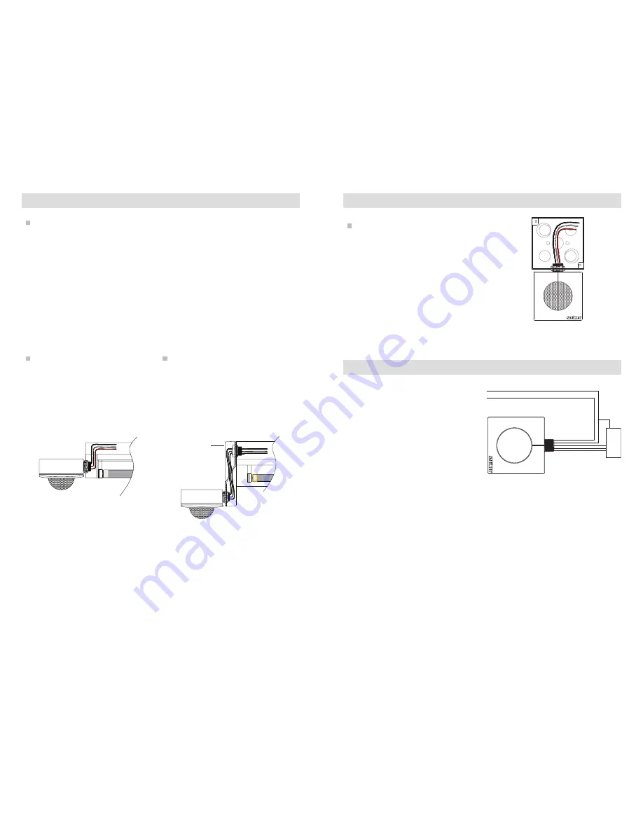
Junction box mounting - HBS 300,
HBS 200
Wiring - HBS 300, HBS 200
When installing, make sure power has
been switched off at the breaker and
check that the circuit is dead with a
voltage tester.
The leads consist of three wires:
Black = line
White = neutral
Red = load
When the HBS-DC is installed:
Violet = DIM +
Gray = DIM -
If in doubt, identify the individual
conductors with a voltage tester or
contact a qualified electrician.
Note 1: Dimming wires are only available
with HBS-DC installed.
Note 2: All HBS and HBS-DC are Class 1
rated.
If mounting to the end of a fixture is not
possible, the HBS 300, HBS 200 can be
mounted to any junction box with a 1/2”
(trade size) knockout. With the HBS 300
and HBS 200, this may be necessary if
the fixture location has an obstruction
that would block the view of the sensor
(for example: racking is directly beneath
the fixture).
Junction
box
HBS 300, HBS 200
HBS 300, HBS 200
LINE (BLACK)
NEUTRAL (WHITE)
NEUTRAL
HOT
LOAD (RED)
DIM + (VIOLET)
DIM – (GRAY)
LOAD
DRIVER
Mounting (continued)


