


9
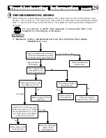
See Figure 16 for switch positions to complete steps 6, 7, and 8.)
____ 6. In the offpeak mode and with the outdoor air sensor (64) disconnected, jumper
sensor connection terminals "W" & "R" of the charge control circuit board (30)
together to perform the following tests:
____ A. Set selector switches to SUMMER and AUTO positions. One
outdoor sensor light should be on. Check the unit's charging circuits
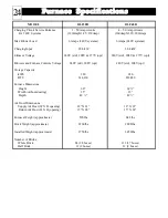
amperages. On 240V systems, they should read:
DLF30B = 40 Amp DLF40B = 53 Amp
____ B. Set selector switches to WINTER and AUTO positions. Two
outdoor sensor lights should be on. Check the unit's charging circuits
amperages. On 240V systems, they should read:
DLF30B = 80 Amp DLF40B = 106 Amp
____ C. Set selector switches to WINTER and HIGH position. Three outdoor
sensor lights should be on. Check the unit's charging circuits
amperages. On 240V systems, they should read:
DLF30B = 120 Amp DLF40B = 160 Amp
____ D. Simulate an onpeak period by changing the status of the blue and blue/white wires. All
heating elements (17) should cycle off.
To perform Step 7, the peak override feature must be enabled. This feature may not be avail
able in your area. Please consult your power company if you are unsure of whether this option is
available to you. If it is available and you desire to enable the feature, contact your power
company for instructions on how to do so. Skip Step 7 if the peak override feature is not avail
able to you.
____ 7. With unit in the onpeak mode, depress the override "START" switch and observe the "OVERRIDE"
indicator light. The light should be illuminated.
____ 8. Remove the jumper between the "W" and "R" outdoor sensor connection terminals and reconnect the
outdoor air temperature sensor (64). Set the selector switches to the AUTO and WINTER positions.
____ 9. Replace the electrical panel cover (46), make certain all fuses and/or circuit breakers are labeled in the
service panel.
____ 10. Present owner with the manual and warranty information. The owner's registration card must be com
pleted and returned to Steffes Corporation to ensure warranty coverage. The owner should retain the top
portion of the card for their records.
____ 11. Take the time needed to instruct the owner on how to operate the system.
23
Installing The Furnace
(cont'd)
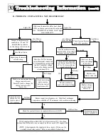
FURNACE FINAL TEST PROCEDURE
____ 1. Check all electrical connections for proper termination placement and do a general inspection for tight
connections, wire routing, etc.
____ 2. Energize the furnace.
____ 3. If the wall thermostat has an anticipator, set the anticipator 0.5 amps.
____ 4. Turn up wall thermostat to bring on a call for heat. Core blower (38) should run on its high speed with a
cold brick core. Because the brick core is cold, the supply air blower (58) will not run in this mode.
____ 5. If the thermostat is equipped with a mode selection switch, set to FAN ONLY, and check for medium high
speed (cooling) supply blower (58) operation.
NOTE
FIGURE 16
NOTE


