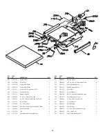
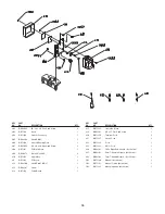
background image

12

15.

ALWAYS

wear eye protection. The operation of any

drum sander can result in debris being thrown into
your eyes,  causing severe eye damage. Everyday
glasses are not safety glasses. Wear safety glasses
that comply with ANSI standard Z87.1

16.

KEEP

hands and clothing away from the rotating

drum, belts and pulleys. 

NEVER

place hands under

the drum or dust cover.

17.

ALWAYS

feed workpieces against the rotation of

the drum.

18.

HOLD

workpieces firmly and be aware of the

possibility of kickback.

19.

DO NOT 

make passes deeper than recommended

in the specifications to avoid damage to the
machine.

20.

NEVER

operate the machine without the dust cover

and belt guard in position.

21.

ALWAYS

stand to one side of the workpiece;

NEVER

stand directly in line with it.

22.

NEVER

force the workpiece into the sander; allow

the feed belt to move the workpiece at the proper
speed.

23.

MAKE SURE

that the workpiece has no loose

knots, screws, nails or other foreign objects that
might damage the feed belt or sanding drum.

24.

ALWAYS

keep bystanders and yourself away from

the infeed and outfeed ends when a workpiece is
fed into the sander.

25.

ALWAYS

keep your hands away from the sanding

drums during operation.

26.

ALWAYS

keep fingers away from the conveyor and

the underside of the workpiece during sander and
conveyor operation.

27.

ALWAYS

adjust the conveyor feed rate and sand-

ing drum height, so when you feed the workpiece
into the sander using light pressure, you do not
overload the sander. 

NEVER

force the workpiece

into the sander.

28.

ALWAYS 

shut the sander down, let the drums

come to a complete stop, and disconnect power or
engage applicable safety-lock devices before you
service, adjust, troubleshoot, or leave the machine
unattended.

29.

ALWAYS

keep this machine in correct adjustment

and properly serviced. 

NEVER

attempt to clear a

jammed workpiece while the sander is running.

30.

ALWAYS

replace the sandpaper when it is worn,

and use only undamaged sandpaper.

31.

NEVER

sand if there is any doubt about the

stability or integrity of the workpiece.

32.

NEVER

sand stock smaller than 1/4” thick or 

6” long.

33.

NEVER

adjust the conveyor belt tracking when the

sanding drums are engaged.

ELECTRICAL REQUIREMENTS

To reduce the risk of electric shock, follow all electri-
cal and safety codes, including the National Electric
Code (NEC) and the Occupational Safety and Health
Regulations (OSHA).  All electrical connections and
wiring should be made by qualified personnel only.

The switch provided with your dual drum sander is
designed to plug in to a 230V outlet.  Since there are
many different configurations for 230V plugs, it is con-
ceivable that the configuration of your 230V outlet may
not match the configuration of the plug.  If this is the
case, you will have to replace the plug with a UL/CSA
approved plug that matches the configuration of your
230V outlet.  

DO NOT

connect the machine to the power source until

you have completed the setup process.

WARNING

!

Summary of Contents for 55220

Page 1: ...User Manual Read and understand this manual before using machine 26 DUAL DRUM SANDER STEEL CITY TOOL WORKS Manual Part No OR71140 C US Model No 55220...

Page 2: ...hy it is backed by one of the longest machinery warranties in the business This drum sander is just one of many products in the Steel City s family of woodworking machinery and is proof of our commitm...

Page 3: ...specifications in this user manual represent your machine at time of print However changes may be made to your machine or this manual at any time with no obligation to Steel City Tool Works INTRODUCT...

Page 4: ...ove warranties in lieu of all other warranties express or implied SCTW shall not be liable for any special indirect incidental punitive or consequential damages including without limitation loss of pr...

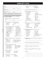
Page 5: ...7 How long have you been a woodworker ___ 0 to 2 years ___ 2 to 8 years ___ 8 to 20 years ___ over 20 years 8 How would you rank your woodworking skills ___ Simple ___ Intermediate ___ Advance ___ Mas...

Page 6: ...FOLD ON DOTTED LINE FOLD ON DOTTED LINE PLACE STAMP HER SteelCityToolWorks 4 Northpoint Court Bolingbrook IL 60440 E 6...

Page 7: ...ng Speed 3 20 S F P M variable Number of Sanding Drums 2 Drum Size 5 x 26 Drum Speed 1550 R P M Dust Ports 2 4 Product Dimensions Footprint 17 3 4 x 43 Length 31 Width 46 Height 53 Weight 485 lbs Ship...

Page 8: ...RE IDENTIFICATION A Dust Ports B Table Elevation Handle Assembly C Conveyor Belt On Off Switch D Conveyor Belt Variable Speed Control E Sanding Drum On Off Switch F Conveyor Belt G Depth Gauge F D E C...

Page 9: ...lly hazardous situation which if not avoided may result in property damage This symbol is used to alert the user to useful informa tion about proper operation of the machine GENERAL SAFETY DANGER NOTI...

Page 10: ...using any machine Carefully check all guards to see that they operate properly are not damaged and perform their intended functions Check for alignment binding or breakage of all moving parts Any gua...

Page 11: ...ormation regarding the safe and proper operation of this tool is also available from the following sources Power Tool Institute 1300 Summer Avenue Cleveland OH 44115 2851 www powertoolinstitute org Na...

Page 12: ...height so when you feed the workpiece into the sander using light pressure you do not overload the sander NEVER force the workpiece into the sander 28 ALWAYS shut the sander down let the drums come t...

Page 13: ...trical work MAKE SURE the circuit breaker does not exceed the rating of the plug and receptacle MINIMUM RECOMMENDED GAUGE FOR EXTENSION CORDS AWG 230 VOLT OPERATION ONLY 25 LONG 50 LONG 100 LONG 0 to...

Page 14: ...parts and the drum sander The protective coat UNPACKING INVENTORY ings can be removed by spraying WD 40 on them and wiping it off with a soft cloth This may need redone several times before all of the...

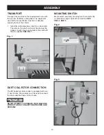
Page 15: ...dle must be aligned Fasten the crank handle to the shaft with the pin supplied SEE FIG 1 Fig 1 A MOUNTING SWITCH Mount switch assembly A using two 10mm bolts B as pictured on upper right side of machi...

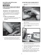
Page 16: ...THE POWER SOURCE BEFORE MOUNTING THE SANDING BELT WARNING MOUNTING NEW SANDING BELTS 1 Insert tab of the belt on the left end of the drum SEE FIG 5 2 Push the left clamp forward to allow the tab to sl...

Page 17: ...ese procedures 1 Remove the right end guard and the front guard 2 Adjust the height position of the motor by turning the M12 nuts A located on the height adjustment bolt SEE FIG 8 3 If the motor becom...

Page 18: ...f the drum IMPORTANT After changing abrasive strips always check and if necessary reset the back drum height The chart below shows the proper settings based upon sanding grits Fig 11 A REAR DRUM SETTI...

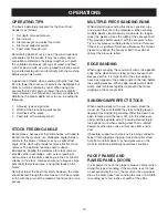
Page 19: ...the machine so it will be sanded in line with the grain of the wood on the final one or two passes MULTIPLE PIECE SANDING RUNS When determining sanding thickness consider cups and crowns that are in...

Page 20: ...ean ing sticks following the manufacturer s directions When cleaning also brush the stick crumbs from the drum while it is still rotating READY TO CUT ABRASIVE STRIPS Description Normal Use 60 Grit Sa...

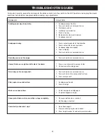
Page 21: ...2 Uneven wear of sanding paper Stock slips on the conveyor belt 1 Too much material is removed at once 2 Too much dust on the conveyor belt surface 3 Worn conveyor belt Shiny spots on sanded surface 1...

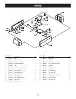
Page 22: ...5 16 Flat Washer 2 10 OR71036 Motor Plate Adjusting Screw 2 11 OR94067 Retaining Ring 6 12 OR71037 Positioning Shaft 2 KEY PART NO NO DESCRIPTION QTY 13 OR71038 Motor Base 1 14 OR71039 Base Shaft 1 1...

Page 23: ...lok Nut 4 126 OR91330 1 4 20 x 1 Hex Head Screw 8 127 OR93868 5 16 18 x 1 2 Hex Socket Head Cap Screw 8 128 OR91658 5 16 Lock Washer 8 KEY PART NO NO DESCRIPTION QTY 130 OR70303 Spec Plate 1 131 OR710...

Page 24: ...Washer 4 2 d a P 5 7 0 1 7 R O 4 1 2 215 OR71076 Micro Adjustment Positioning Plate 2 KEY PART NO Y T Q N O I T P I R C S E D O N 4 2 0 2 6 g n i r a e B 1 8 0 4 9 R O 6 1 2 217 OR94082 5 16 18 x 4 He...

Page 25: ...3 8 Pan Head Screw 4 350 OR94088 Nut 4 351 OR71104 Bushing 2 352 OR94089 Set Screw 4 KEY PART NO NO DESCRIPTION QTY 353 2 w e r c S g n i t s u j d A o r c i M 5 0 1 1 7 R O 354 2 r e h s a W 0 9 0 4...

Page 26: ...Board 1 412 OR94100 Strain Relief 6R 3 1 413 OR94107 Screw 3 414 OR71134 Cabel Guard 1 KEY PART NO NO DESCRIPTION QTY 415 OR71135 Insulation Board 1 416 OR94101 M5 x 15 Flat Head Screw 2 430 OR71136...

Page 27: ...5 Year Warranty STEEL CITY TOOL WORKS www steelcitytoolworks com N 1 877 SC4 TOOL 1 877 724 8665 27...

Page 28: ......
Reviews: