background image

6

A

B

C

I

J

E

K

D

F

G

H

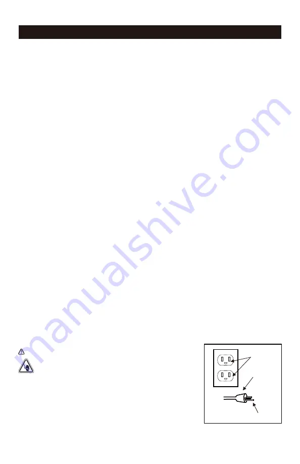
Figure 1 

DANGER

Grounded 

outlet 

Grounding Pin 

Plug 

PARTS DESCRIPTION

Electric Motor
The motor is used to power the pump. It is equipped with a thermal overload protector. If the motor 

overheats for any reason, the thermal overload protector will shut it down in order to prevent the motor 

from being damaged.
Air Compressor Pump
The pump compresses the air and discharges it into the tank via the piston that moves up and down in the 

cylinder.
Safety Valve
This valve is used to prevent the compressor from building too much pressure. If the pressure reaches the 

preset level of the motor, it will automatically pop open. You can also pull the ring on the valve to open 

manually.
ON/OFF Switch
This switch turns on the compressor and is operated manually.When in the ON position, it allows the 

compressor to start up or shut down automatically, without warning, upon air demand.ALWAYS set this 

switch to OFF when the compressor is not being used and before unplugging the compressor.
Air Pressure Regulator
The regulator is used to adjust the pressure inside the line to the tool that is being used. Turn the knob 

clockwise to increase the pressure and counter-clockwise to decrease the pressure.
Tank Pressure Gauge
The gauge measures the pressure level of the air that is stored in the tank. It cannot be adjusted by the 

operator and it does not indicate the pressure inside the line.
Outlet Pressure Gauge
The gauge measures the regulated outlet pressure.
Quick Coupler
The quick coupler is connected to a quick connector which is connecting to air hose.
Drain Valve
The drain valve is used to remove moisture from the air tank after the compressor is shut off.
Air Tank
The tank is where the compressed air is stored.
Power Cord
This product is for use on a nominal 120-volt circuit and should be grounded. A cord with a grounding plug 

as illustrated must be used. Make sure that the product is connected to an outlet that has the same 

configuration as the plug (see Figure 1). No adapter should be used with this product. Check with a 

licensed electrician if the grounding instructions are not understood or there is doubt as to whether the 

product is properly grounded. Do not modify the the plug provided. If it will not fit the outlet, have the 

proper outlet installed by a licensed electrician.

Improper installation of the grounding plug will result in a risk of 

electric shock. If repair or replacement of the cord or plug is 

necessary, do not connect the grounding wire to either flat blade 

terminal. The grounding wire is in the green outer surface.

Summary of Contents for 3300382

Page 1: ...ressor To Reduce The Risk Of Injury User Must Read And Understand Operator s Manual Save These Instructions For Future Reference Toll Free Helpline OPERATOR S MANUAL CAUTION 1 888 899 0146 Product Mod...

Page 2: ...s Read all instructions and follow them with use of this product CFM Cubic Feet per Minute This compressor is rated in accordance with ISO 1217 displacement compressors acceptance tests TECHNICAL SPEC...

Page 3: ...sure that the procedure work method or operating technique that you choose does not render the compressor unsafe The safety alert symbol indicates a potential hazard to personal injury A signal word D...

Page 4: ...erious injury Risk of serious eye injury Always wear ANSI Z87 1 approved safety goggles when using air compressor Do not spray any part of the body Shock risk could result in death or serious injury O...

Page 5: ...r Pressure Regulator G Outlet Pressure Gauge F Tank Pressure Gauge D ON OFF Switch H Quick Coupler B Air Compressor Pump A Electrical Motor J Air Tank I Drain Valve C Safety Valve G J A D C H B K E I...

Page 6: ...wise to decrease the pressure Tank Pressure Gauge The gauge measures the pressure level of the air that is stored in the tank It cannot be adjusted by the operator and it does not indicate the pressur...

Page 7: ...air hose 1 to the compressor s quick coupler 2 with the quick conncetor 3 Fig B Air hose and quick connector are not provided need to be purchased sepa rately Apply plumber s tape on all the threads...

Page 8: ...ng in the unit is noly requiresd prior to first use Fig F After 30 minutes turn off the ON OFF switch Close the tank drain valve 1 by turning it clockwise Fig G Set the ON OFF switch to the ON positio...

Page 9: ...rd 2 Fig K Set the ON OFF switch to the ON position and allow the tank pressure to build Motor will stop when tank pressure reaches cut out pressure Turn the air pressure regulator knob clockwise unti...

Page 10: ...ect and wind up the power cord Clean the ventilation openings on the motor enclosure with a damp cloth Drain all moisture from the tank Pull the pressure safety valve to release all pressure from the...

Page 11: ...gauge and cord length Turn the air compressor off unplug the power cord and wait until the motor has cooled down Plug in the power cord only after the motor has cooled down and wait at least 5 minutes...

Page 12: ...equate Cooling surfaces are dirty The valve is leaking Check the fittings with soapy water Tighten or reseal leaking fittings apply plumber s tape on threads Do not over tighten Close the drain valve...

Page 13: ...13 EXPLODED VIEW...

Page 14: ...ansfer Tube Clamp Screw M4x12 Screw M4x10 Capacitor Shroud Capacitor Head Screw M5x12 Elbow Fitting 1 1 1 1 1 2 1 3 1 2 1 2 2 1 1 1 6 2 4 1 Description Qty No 21 22 23 24 25 26 27 28 29 30 31 32 33 34...

Page 15: ...dress below and call 1 888 899 0146 for instructions prior returning this item to the store or sending back to We will inspect the product and contact you within 72 hours to give you the results of ou...

Reviews: