D2133_01_04 CN5082 SEM110 User Guide
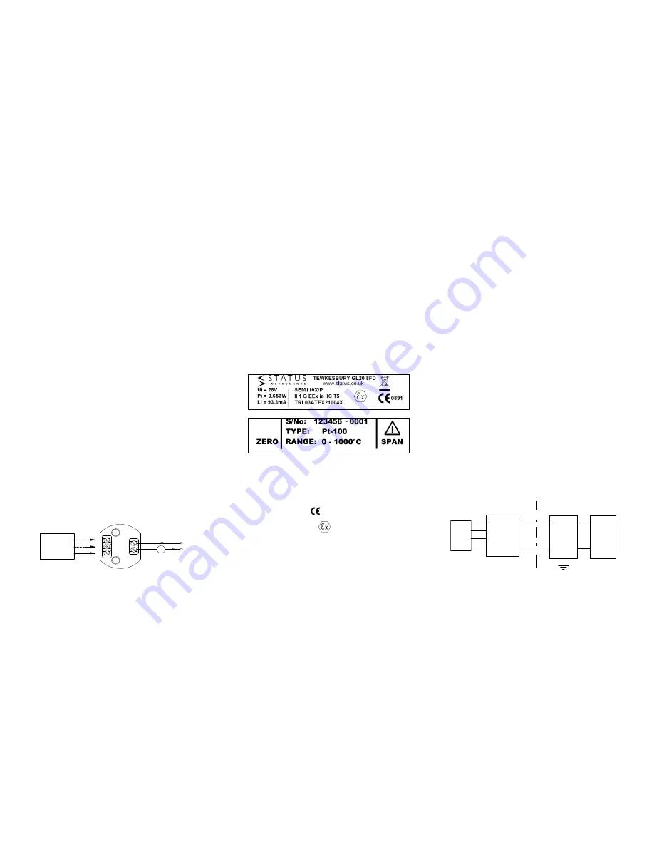
The Pt100 sensor shown as an example would normally take the form of a
probe assembly with a three wire output. Refer to connection drawing for
other connection types. The output loop shows a 24 V DC power supply
used to provide loop excitation, the transmitter and a load all connected in
series. The load symbol represents other equipment in the loop e.g.
indicators, controllers, loggers etc. Sometimes these instruments come
with the 24 V supply built in as standard, this simplifies wiring and reduces
cost. Care must be taken when designing the (4 to 20) mA circuit to
ensure that the total burden of the loop, that is the total voltage
requirements of all the equipment in the loop added together, does not
exceed the power supply voltage. If a number of instruments are
connected in the loop, ensure that only one instrument is tied to ground.
Grounding the loop at two points will result in shorting out part of the loop
and therefore any instruments in that part of the loop will not operate.
4.0 Calibration
Calibration is only recommended when the user has access to suitable
equipment, together with a reasonable knowledge of instrumentation
calibration techniques. The following instructions act as a guideline to
calibration.
4.1
A precision calibrator will be required, to simulate the type of
sensor the transmitter is designed for, together with a set of
tables giving the sensor output against process variable, (e.g.
resistance against temperature for a PT100 sensor). A
precision digital current meter together with a 24 V DC supply
will also be needed. Read the SEM110 label to establish the
transmitter range i.e. the process variable input for 4 mA and
20 mA. The side label also indicates the location of the span
and zero pots.
4.2
Connect calibrator to input terminals, using the correct
compensation wire for thermocouples inputs and three wire
connection for RTD inputs. Connect the output positive to +24
V, negative to 0 V via current meter. Turn power on.
4.3
Set simulator to 4 mA process variable and adjust ZERO
trimmer for 4.000 mA output. ±0.002mA
4.4
Set simulator to 20 mA process variable and adjust SPAN
trimmer for 20.000 mA output ±0.002 mA.
4.5
Repeat steps 4.3 and 4.4 until both points are in calibration.
4.6
Turn power off and remove calibration equipment.
5.0 SEM110X\* VERSIONS - FOR USE IN POTENTIALLY EXPLOSIVE
ATMOSPHERES
5.1 ATEX Certificate
The SEM110X/* models has been issued with a EC-type examination
certificate, confirming compliance with the European ATEX directive
94/9/EC for :-
Intrinsic safety
II 1 G EEx ia IIC T5.
The equipment bears the Community Mark and subject to local codes of
practice, may be installed in any of the European Economic Area (EEA)
member countries. The SEM110X housing is coloured light blue to identify
the equipment as suitable for Hazardous area use. The equipment must
be installed and maintained in accordance with local requirements for
electrical equipment for use in potentially explosive atmospheres, eg
EN60079-14 & EN60079-17. This instruction sheet describes installation
which conforms with BS EN60079-14 & BS EN60079-17 Electrical
Installation in Hazardous Areas. When designing systems outside the UK,
the local Code of Practice should be consulted.
5.2 Atex marking
Common Information
Manufacturer
Status Instruments Ltd
Type Number
SEM110X/P
SEM110X/TC
SEM110X/W
CE Marking
0891
Explosive Protection Marking
(Type ia) Intrinsic Safety
II 1
Equipment Group and category
G
Type of explosive atmosphere (Gas)
EEx ia IIC T5
Intrinsic safety information
TRL03ATEX21004X
Certificate reference
5.3 Special Conditions for Safe Use
As indicated by the Certificate Reference "X" suffix, special conditions
apply for safe use for both intrinsic safety and energy limitation
applications. They are as follows:-
5.4 Zones, Gas Groups, and T rating.
When connected to a approved system the SEM110X/* may be installed
in:-
Zone 0
explosive gas air mixture continuously present
Zone 1
explosive gas air mixture likely to occur in normal use
Zone 2
explosive gas air mixture not likely to occur and if it does, it will
only occur for a short time.
Be used in gas groups;-
Group A
propane
Group B
ethylene
Group C
hydrogen
Allowable Temperature classification / ambient temperature:-
Intrinsic safety (Type ia)
Class
T5 100°C : Ta = -20°C to +40°C
T4 135°C : Ta = -25°C to +55°C
T3 200°C : Ta = -25°C to +55°C
T2 300°C : Ta = -25°C to +55°C
T1 450°C : Ta = -25°C to +55°C
5.5 Environmental Protection
This equipment must be housed in an enclosure which provides a degree
of protection of at least IP54. The enclosure must be suitable for the
atmosphere and environment in which it is installed (eg If of plastic
material, must be resistant to chemical corrosion, UV light, temperature,
humidity etc.)
5.6 Maintenance
This intrinsically safe equipment contains no user serviceable, adjustable
or replaceable parts. No attempt should be made to repair a faulty
SEM110X/* transmitter, all units must be returned to the manufacture for
repair or replacement. Attempt service or
replacement of parts may
invalidate the explosive protection features of the equipment.
5.7 Connection Diagram
They equipment must be electrically connected as shown below:-
SEM110X\* Working Parameters
Ui
28 V
I i
93.3 mA
Pi
0.653 W
Ci
0 nF
Li
0 uH
-
SEM 110X
C ALIBR ATO R
D C
+
-
+ 24V
A
SENSOR
SEM110X
3
1
4
5
2
BARRIER
Maximum
output
Vo 30V
Io 100mA
Po 750mW
DC
SUPPLY
+
-


