D2614-01-03 CN5819
5.1~USB CONFIGURATION
Using the USBSpeedLink software to program a new configuration into the device
work from left to right through the option tabs.
The USB port is located inside the housing on the rear panel.
Configuration steps
Install and run the USBSpeedLink software
Select the correct programming page in the software (follow any on screen
safety precautions)
Connect the USB lead to the PC, connect the USB lead to the device
Read the unit configuration into the software
Re-configure or adjust configuration options as required
Send the new configuration to the unit
5.1.1~Sensor option tab
Use this tab to pre-set RH and temperature values; this can be used for system testing
and diagnostics.
5.1.2~Relay tab (showing live readings in the “Data” section)
Use this tab to set the relay controls.
Relay options for %RH, temperature, dew point and delta t. source
Set point
Dead band
Low alarm
Low control (inverted low alarm)
High alarm
High control (inverted high alarm)
Alarm inside band
Alarm outside band
Low battery alarm
Alarm off
A diagram will display to show alarm type function
5.1.3~Basic display options tab
Use this tab to select the display value options, °C or °F and LED function
!
5.1.4~Advanced display options tab
Use this tab to set up the advance messaging options.
5.1.4~Advanced display options tab (continued)
6 user set ranges/bands can be set for either %RH, temperature, dew point or delta t.
Each range can have 1 or 2 messages assigned that will display on the screen when
the input source signal is within the set band. Also, the LED can be set to flash, within
the selected range.
Up to 7 user messages can be entered or pre-set messages can be used.
Relay in or out of alarm trip can also be used to prompt specific messages to be
displayed.
5.1.5~Other display options tab
Use this tab to set the “Tag” and “Contact” free type fields stored to the device. A
passcode to protect the device log from being overwritten by an Android device can be
added.
Longitude and latitude data can be entered, this will show in the log files and can help
identifying data logs recorded from multiple devices.
6~DATA LOGGING
USB and Android NFC software allows the user to read existing logs, change the log
manifest, start a new log, synchronise the instrument clock and reset the
maximum/minimum readings.
Logs can run to a fixed number and stop or continually roll over, up to 5000 log points
can be recorded. The start of the log can be delayed up to one month.
Data from can be viewed on screen as a graph or table and can also be saved to a
csv file.
6~1 USB LOGGING
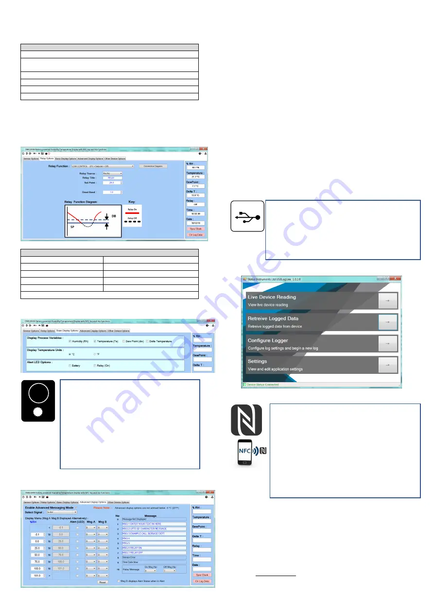
USB LogLink software
6~2 NFC LOGGING
Status Instruments Ltd, Status Business Park, Gannaway Lane, Tewkesbury,
Gloucestershire, UK, GL20 8FD,
Web Page: www.status.co.uk, Email: [email protected]
Technical Support: [email protected]
Tel: +44 (0) 1684 296818, Fax: +44 (0) 1684 293746
USB LOGGER INTERFACE (connector inside housing)
The USB interface allows the instrument to communicate with a PC running
the USBLogLink software
The prime function of the interface is to read logged data from the device
using free software available to download.
The software allows the user to read existing logs, change the log manifest,
start a new log, synchronise the instrument clock and reset the
maximum/minimum readings.
USBLogLink is available from the manufacturer or supplier.
NFC LOGGER INTERFACE
The NFC interface allows the instrument to communicate with an Android
device using NFC connectivity.
The prime function of the interface is to read logged data from the device
using a free app, which is available for downloading to Android devices.
The app allows the user to read existing logs, change the log manifest,
start a new log, synchronise the instrument clock and reset the
maximum/minimum/average readings. Logs can run to a fixed number and
stop or continually roll over, up to 5000 log points can be recorded. The
start of the log can be delayed up to one month.
Note:
For larger logs the data may take over a minute to fully download via
the NFC interface.
Note:
Not all Android devices fully implement the near field communication
(NFC) standard and may not hold the full 5000 log points.
Download Status Instruments apps from the Google Play Store
MULTIFUNCTION ALERT LED
The alert LED normal state is off, on alert the LED will emit an
intense white light pulse every 5 seconds. The LED can be
programmed to pulse on any of the following combined events:
Mode
Description
No events The LED never operates, extending battery life.
(Factory default setting)
Battery
Alert on low battery detect.
Trip
Alert when relay trip is on.
Temperature In advanced mode only the alert LED can be made to
alert in any one of eight user-set temperature bands. Example, to
alert operator when temperature is outside a safe operating range.
The function of the alert LED can be further enhanced with the option
of displaying an alert message in advanced display mode.


