Starwin V9 OTM45 Installation And User Manual Download Page 22


22


Copyright © 2021 China Starwin


6.3


System M&C by ACU Front Panel Controls


The ACU display menu has hierarchical structure, divided into four submenu items: "

Status 

Show

", "

System Settings

", "

Version Info

" and "

Language

", as shown at Figure 6-3, with 

corresponding functionality of each of them.  
 
 
NOTE: Use the Up/Down and Left/Right ACU front panel buttons to navigate through  
             ACU Display menu items. 
             Use Item Selection/Value Confirmation “OK” button to select a highlighted menu 
             item or parameter for viewing its current status or editing its value. 

     Use the “Return to Previous Menu” button to exit current menu item  

             to a previous one. 

 The display cursor sign  

 indicates which submenu item or parameter value is 

             accessible by pressing the “Navigate to the Right” button. 

            The display cursor sign  

 indicates which submenu item or parameter value is 

             accessible by pressing the “Navigate to the Left” button. 
 
 
For the first time of the system use, it is necessary to set up several its parameters to initiate the 
antenna operation, satellite searching, pointing and acquisition.  


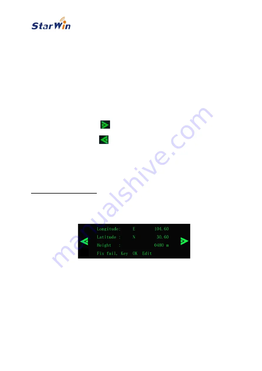
GNSS Information interface:  

 
The system automatically recognizes its geographical position under the "open sky", 
when it is able to receive GNSS signals. The detailed positioning information is 
displayed as shown at Figure 6-4. 


Figure 6-4: Detailed Positioning Information Display 

 
In case when the GNSS receiver fails to provide the positioning information navigate to “

Fix 

fail

” by means ACU front panel navigation and selection buttons.  

Confirm or edit the position displayed at GNSS Information interface by navigating to “

OK

" or 

Edit

” by means ACU front panel navigation and selection buttons. 


NOTE: Use the ACU front panel “Left” and “Right” navigation keys to navigate between 
              System State, GNSS and Satellite Information menu items at the ACU Display.  
             Use the ACU front panel “OK” key to edit and/or confirm the selection. 


Summary of Contents for V9 OTM45

Page 1: ...V9 OTM45 Antenna System Installation and User Manual Name mobile satellite communication terminal Model Number V9 OTM45 Revision 1 3...

Page 2: ...equipment supplied with it Warranties and Disclaimers All China Starwin Science Technology Co Ltd China Starwin products purchased from China Starwin or through any of its authorized by China Starwin...

Page 3: ...RESS OR IMPLIED WARRANTY OF FITNESS FOR HIGH RISK ACTIVITIES b PURCHASER S SOLE REMEDY FOR BREACH OF THE EXPRESS WARRANTIES ABOVE SHALL BE REPLACEMENT OR REFUND OF THE PURCHASE PRICE AS SPECIFIED ABOV...

Page 4: ...nts and their cables It is necessary to read the instructions carefully before using the V9 OTM45 The V9 OTM45 usage shall be carried out in accordance with the described steps and methods to ensure t...

Page 5: ...tained herein is merely descriptive in nature and does not constitute an offer for the sale of the product described herein Any changes or modifications of the equipment including opening of the equip...

Page 6: ...ing 13 5 1 V9 OTM45 Unpacking 13 5 2 Mounting Antenna on a Flat Platform 15 5 3 Mounting Antenna on Vehicle Roof Rails or Roof Rack 16 5 4 Mounting Antenna Directly on Vehicle Roof 17 5 5 Cables Layin...

Page 7: ...eliable communication system which can be used anywhere and at any time The China Starwin V9 OTM45 system provides a moving vehicle by broadband communication with high throughput comparable with wire...

Page 8: ...ited continuous rotation Elevation Range 0 90 Polarization Range 0 270 Controlled by software Tracking Accuracy 0 3 Tracking Mode Inertial measurement combined with signal tracking Tracking Rate Azimu...

Page 9: ...LAN Cable 5m 1 Equipment commissioning use 6 Bonding adapter plates Optional 4 Stand 7 Wooden case 1 Stand Feasibility of any required customized configuration can be investigated 3 2 Unpacking and I...

Page 10: ...it Both system parts are connected by a single coaxial cable which transfers received signals from Out cabin Unit to the In cabin Unit at L band and transmitted signals in the opposite direction at In...

Page 11: ...in Unit The Out cabin unit equipment is installed at the vehicle roof All Out cabin unit elements are inside the radome as shown at Figures 4 4 and 4 5 Figure 4 4 Out cabin Unit Radome Layout Figure 4...

Page 12: ...ensors 11 Elevation motor Creates torque for antenna movement by Elevation angle 12 Elevation drive Transmits torque from Elevation motor to antenna 13 Azimuth motor Creates torque for antenna movemen...

Page 13: ...ustomer order and the may differ according to the included modem and additional accessories The system can be supplied with the integrated modem or without it Customers can use modem supplied by contr...

Page 14: ...horizontal surface and open the cover Remove four nuts and four screws fixing the antenna assembly to the wooden packing case Take out the antenna assembly from the wooden packing case Figure 5 2 Unp...

Page 15: ...icle roof The antenna assembly mounts directly to the platform and is secured to it with four M8 screws NOTE Do not bend the bottom plate of the antenna radome during the installation process If neces...

Page 16: ...ix the crossbars with the antenna on roof rails or on roof rack NOTE It is recommended to use thread locking adhesive like Loctite Threadlocker Blue 242 or its analog to secure bolts and nuts from acc...

Page 17: ...e from paint and dust at places where it will contact the bonding adapter plates Glue the bonding adapter plates to the roof of the car with structural glue NOTE Do not bend the bottom plate of the an...

Page 18: ...ver Coax supply from ACU to the Out cabin Unit Transfer of receiving L band signals from Out cabin Unit to ACU Transfer of transmitting IF Intermediate Frequency signals from ACU to Out cabin Unit 2 L...

Page 19: ...ceed to step 7 However if ACU is designated for use with an external modem execute the following steps 5 Connect the Bluetooth and Wi Fi antennas to their corresponding interfaces located at ACU rear...

Page 20: ...20 Copyright 2021 China Starwin 6 System Initialization and Operation 6 1 ACU front Panel Controls ACU front panel controls are shown at Figure 6 1 Figure 6 1 ACU Front Panel Controls...

Page 21: ...ication during the system initialization Upon initialization completion ACU will display the system management main menu as shown at Figure 6 3 Figure 6 3 System Management Main Menu There are three o...

Page 22: ...cessible by pressing the Navigate to the Left button For the first time of the system use it is necessary to set up several its parameters to initiate the antenna operation satellite searching pointin...

Page 23: ...ity at the corresponding interface of the built in modem RX Receiving TX Transmitting NET Connection to Network over Satellite GPS the green fill of circular points indicates the successful reception...

Page 24: ...parameters definition such as Satellite Setting Protection Function Modem Setting and Factory Reset Figure 6 7 System Setting Configuration Display Satellite Setting interface Satellite Setting menu...

Page 25: ...gure 6 10 and press OK key for confirmation Figure 6 10 Satellite Record Adding or Editing Display NO number of the record is added automatically Longitude satellite position at geostationary orbit Mo...

Page 26: ...tion shown at Figure 6 13 by pressing the Left and Right navigation keys at the ACU Front Panel and press OK button for confirmation Figure 6 13 Satellite Record Deletion confirmation interface Protec...

Page 27: ...item from the System Settings menu Figure 6 7 moving the highlighting to it by navigation keys at the ACU Front Panel and pressing OK button for confirmation The Modem Settings submenu Figures 6 15 an...

Page 28: ...er Out of Network Timer which starts every time the receiving signal is lost while the ABS is turned on ON suppresses the Out of Network Timer activation at the modem while the ABS is turned on The mo...

Page 29: ...es the device version number IDU version indicates the master control software version number ACU version indicates the ACU software version number This information is used mainly for equipment troubl...

Page 30: ...C Application software does not require installation However for normal V9 OTM45 M C Application operation Microsoft NET Framework 4 7 2 should be installed If Microsoft NET Framework 4 7 2 environmen...

Page 31: ...address is 192 168 16 101 To communicate with V9 OTM45 Navigate to Control Panel Network and Internet Network Connections Local Area Connection Select Internet Protocol Version 4 TCP IPv4 Click Proper...

Page 32: ...en the unzipped folder V9 OTM45_Host computer shown at Figure 7 6 Figure 7 6 Running Environment Open soft folder as shown at Figure 7 7 Figure 7 7 Running Environment Run the V9 OTM45 M C Application...

Page 33: ...V9 OTM45 ACU by entering the ACU IP Address Port Number and clicking the Connect button Figure 7 10 The default V9 OTM45 ACU IP Address is 192 168 16 101 The default port is 5001 Upon successful conne...

Page 34: ...ntrol section located at the right side of the application interface under the Menu bar NOTE The Modem functionality indication and Beam Switching control section is active for systems with built in m...

Page 35: ...Figure 7 11 which closes the Application Figure 7 11 File Submenu Exit Item Settings submenu includes items shown at Figure 7 12 ACU IP Configuration Search Settings Modem Settings Service Mode Batter...

Page 36: ...ing Figure 7 15 Satellite Longitude satellite position at geostationary orbit Values E East or W West Range 0 180 Mode the internal receiver operational mode Values Beacon DVB TV Carrier Signal Carrie...

Page 37: ...7 16 Modem Selection Battery Protection Settings submenu item allows definition of battery protection voltage as shown at Figure 7 17 Figure 7 17 Battery Protection Settings Service Mode submenu item...

Page 38: ...bug submenus as shown at Figure 7 20 Figure 7 20 Factory Submenu Items Factory Settings submenu item selection opens form shown at Figure 7 22 allowing V9 OTM45 component parts Serial Numbers reading...

Page 39: ...at Figure 7 24 Figure 7 24 Flash Update Form To perform ACU or Master Control version upgrade 1 Enter the current ACU IP address and communication port number into corresponding fields of the Flash Up...

Page 40: ...ction of M C Application Help submenu includes Support and About items as shown at Figure 7 25 Support item selection provides the Technical Support Department contact information About item selection...

Page 41: ...em receiving status TX Indicates built in modem transmitting status NET Indicates the built in modem successful satellite network connectivity SNR Shows received signal to noise ratio of the built in...

Page 42: ...Carrier receiver Values range 0 10V GNSS Lock indicator green color means that positioning information is successfully received from GNSS satellites Latitude displays Latitude of the current positioni...

Page 43: ...displays the selected Polarization of the receive channel LNB LO Frequency MHz displays the currently selected LNB LO frequency RX Channel Frequency MHz displays the currently configured receive chan...

Page 44: ...lean cloth Weekly Cables Available damages and fixation loosening checking Weekly Cables Waterproof condition of outdoor connectors and cables checking Monthly Antenna Robustness of the fastening betw...

Page 45: ...64 5710 M 707 953 2589 E garrett x2n com W x2nsat com X2nSat Inc Petaluma Satellite Gateway and Network Operations Center 1310 Redwood Way Suite C Petaluma CA 94954 Las Cruces Satellite Gateway and Ne...

Page 46: ...o 2 Daqing Road Lianhu District Xi an 710082 China Garrett C Hill Chief P 707 664 5710 M 707 953 2589 E garrett x2n com W x2nsat com X2nSat Inc Petaluma Satellite Gateway and Network Operations Center...

Page 47: ...outlet on a circuit different from that to which the receiver is connected Consult the dealer or an experienced radio TV technician for help Danger FCC Radio Frequency Exposure Information In order t...

Page 48: ...on 1 To avoid electrical shock do not perform any servicing unless you are qualified to do so 2 Before connecting this instrument to a power source make sure that the voltage of the power source match...

Reviews: