background image

1.

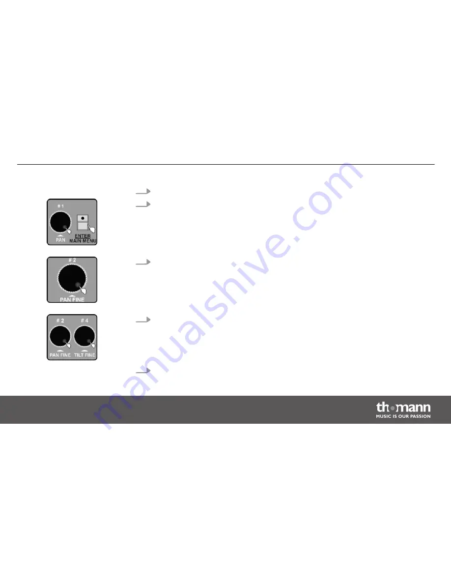
Call up the main menu.

2.

Turn jog wheel # 1 until 

‘10. Auto remote address’

 is displayed. Press the

[ENTER / MAIN MENU]

 button to activate this function.

3.

Turn jog wheel # 2 to change the default setting 

‘[NO]’

 to 

‘[Yes]’

. If the display shows

‘[NO]’

 and you press the 

[ENTER / MAIN MENU]

 button, the unit will close this submenu. If

the display shows 

‘[YES]’

 and you press the 

[ENTER / MAIN MENU]

 button, the address

dialogue opens up.

4.

Then use jog wheel # 2 to select the device number from 001-170 and press the number

buttons 

[1 – 20]

 to select the desired address. All LEDs blink three times to confirm, and

the address of the respective device is displayed. This means that the corresponding

address has been transferred to the device.
Proceed accordingly using jog wheel # 4.

5.

Repeat steps 3–4 to enter the addresses of other devices.

Operating


DMX Invader 2420 MK2

51

Summary of Contents for DMX Invader 2420 MK2

Page 1: ...DMX Invader 2420 MK2 DMX controller user manual...

Page 2: ...Musikhaus Thomann e K Treppendorf 30 96138 Burgebrach Germany Telephone 49 0 9546 9223 0 E mail info thomann de Internet www thomann de 17 10 2013...

Page 3: ...nections and operating elements 17 6 Operating 27 6 1 Setting menu 27 6 2 Programming mode 65 6 3 Function mode 124 6 4 Fogger operation 137 6 5 Strobe operation 139 7 MIDI functions list 143 8 Notes...

Page 4: ...10 Protecting the environment 159 Table of contents DMX controller 4...

Page 5: ...e that it is available to all persons using this device If you sell the device include the manual for the next owner Our products are subject to a process of continuous development We therefore reserv...

Page 6: ...result in death or serious injury if it is not avoided NOTICE This combination of symbol and signal word indicates a possible dangerous situation that can result in material and environmental damage...

Page 7: ...to be improper and may result in personal injury or property damage No liability will be assumed for damages resulting from improper use This device may be used only by persons with sufficient physica...

Page 8: ...t detach any small parts e g knobs or the like from the unit They could swallow the pieces and choke Never let children unattended use electrical devices DANGER Electric shock caused by high voltages...

Page 9: ...ify the mains cable or the plug Failure to do so could result in electric shock death or fire If in doubt seek advice from a regis tered electrician NOTICE Risk of fire Do not cover the device nor any...

Page 10: ...cting the device ensure that the input voltage AC outlet matches the voltage rating of the device and that the AC outlet is protected by a residual current circuit breaker Failure to do so could resul...

Page 11: ...to 50 user defined devices n 10 preprogrammed editable Movements with adjustable phase shift n 60 programmable Chases 200 scenes per Chase n 1200 programmable Scenes 60 banks 20 memory slots n 20 Pre...

Page 12: ...position can be defined n Password protection available n Standard MIDI port n USB port for gooseneck lamp lamp included n USB port for software updates data backup and importing saved banks n Contro...

Page 13: ...g transportation or storage use the original packaging or your own packaging material suitable for transport or storage respectively Establish all connections as long as the unit is switched off Use t...

Page 14: ...ice 1 Con nect the output of the first DMX device to the input of the second one and so on to form a daisy chain Always ensure that the output of the last DMX device in the daisy chain is termi nated...

Page 15: ...Invader For example to assign the 10 channels of a device to the channel faders CH1 CH10 of the Invader you have to set the DMX address of the device to be controlled to 1 The next channel fader CH11...

Page 16: ...The DMX address defines the number of the first DMX control channel of a device 1 512 Installation DMX controller 16...

Page 17: ...5 Connections and operating elements Front panel Connections and operating elements DMX Invader 2420 MK2 17...

Page 18: ...ture number channel list on page 23 the first device gets DMX address 1 the next one 25 the next one 49 and so on you can press the FIXTURE button and then use the number buttons 1 20 to address the i...

Page 19: ...ed Cue sequence of several Chases 9 OVERRIDE Button for subsequently selecting a programmed scene that overrides the running show 10 BANK Button for subsequently selecting a scene 11 CENTER If you hav...

Page 20: ...the sound controlled mode In programming mode this button initiates copying 15 TAP INSERT In function mode automatic only you can adjust the speed of certain procedures by pressing this button repeate...

Page 21: ...s activates the BLACK OUT function which can be disabled by briefly pressing this button once again 18 USB Light The USB port is used exclusively to connect a USB lamp 19 Fader Use these faders to adj...

Page 22: ...tons 11 20 on up to 20 memory pages Cue To select and programme up to 60 Cues Chase To select and programme up to 60 Chases Override To select and programme up to 20 Overrides Bank To select and progr...

Page 23: ...se encoders you perform a lot of adjusting and selecting when operating of the device The following table shows you which DMX channels are assigned to the 24 channel faders by pressing the number butt...

Page 24: ...1 1 24 11 241 264 2 25 48 12 265 288 3 49 72 13 289 312 4 73 96 14 313 336 5 97 120 15 337 360 6 121 144 16 361 384 7 145 168 17 385 408 8 169 192 18 409 432 9 193 216 19 432 456 10 217 240 20 457 48...

Page 25: ...cord to an AC outlet that provides the voltage specified in the Technical Data 2 ON OFF switch Turns the unit on or off 3 USB USB port for software updates data backup and importing saved banks Rear...

Page 26: ...ice receives MIDI data MIDI THRU feeds the incoming MIDI data to the next MIDI device 7 DMX OUT These two terminals send DMX signals to DMX capable devices Use a cable with 3 pin XLR connectors to con...

Page 27: ...s will appear on the display Once this is completed the device can be used 6 1 Setting menu 1 Enter the programming mode by holding down the PROGRAM button for 2 seconds The LED of the PROGRAM button...

Page 28: ...s the following 17 sub menus 1 Create a new fixture profile 2 Modify a fixture profile 3 Delete a fixture profile 4 Patch a fixture 5 Reverse channel setup 6 Fade mode select 7 Blackout mode select 8...

Page 29: ...17 Channel value display mode Select the desired menu item with jog wheel 1 and press the ENTER MAIN MENU button to enter the respective submenu for editing Press the ESC CLEAR button to return to th...

Page 30: ...ds 6 1 1 Create a new fixture profile If you create profiles for the used device you can replace the fader channel number in the display by the description for the actual function of the fader on the...

Page 31: ...e of the fixture Rotate jog wheel 2 to change the cursor position Turn Jog wheel 4 to change the character You can choose from 26 letters and 10 numbers as well as the special character The max length...

Page 32: ...gnment for the current channel e g PAN TILT DIM etc The attributes A amber and W white are supported 6 Press the ENTER MAIN MENU button to confirm 7 Turn jog wheel 2 to select the profile collection S...

Page 33: ...k three times and thereby indicate that you have successfully edited a device profile 9 Repeat steps 3 8 to create up to 50 device profiles 10 Press the ESC CLEAR button to return to the previous menu...

Page 34: ...MAIN MENU button to activate this function 3 Turn jog wheel 4 to select a profile from the STAIRVILLE profile collection Turn jog wheel 3 to select a profile from the profile collection of another ma...

Page 35: ...heel 2 to change the cursor position Turn Jog wheel 4 to change the character You can choose from 26 letters and 10 numbers as well as the special character The max length of the device name is 16 cha...

Page 36: ...urrent channel e g PAN TILT DIM etc 8 Repeat steps 3 7 to modify other fixture profiles 9 Press the ESC CLEAR button to return to the previous menu level If you have modified a profile you must reassi...

Page 37: ...e profile is displayed Press the ENTER MAIN MENU button to activate this function 3 Turn jog wheel 4 to delete a profile from the STAIRVILLE profile collection Turn jog wheel 3 to delete a profile fro...

Page 38: ...lay shows Delete the fixture NO 5 Turn jog wheel 2 to change to Yes 6 Press the ENTER MAIN MENU button all LEDs blink three times and thus confirm the successful deletion 7 Repeat steps 3 6 to delete...

Page 39: ...eturn to the previous menu level 6 1 4 Patch a fixture This feature allows you to assign a previously created profile to one of the Number buttons 1 20 that allow you to address the connected devices...

Page 40: ...button to activate this function 3 Press the number button 1 20 to select the device that you want to be patched 4 Turn jog wheel 4 to select a profile from the STAIRVILLE profile collection Turn jog...

Page 41: ...h additional device devices 7 Press the ESC CLEAR button to return to the previous menu level 6 1 5 Reverse channel setup With this function you can reverse individual fader functions so that e g push...

Page 42: ...activate this function 3 Press the number button 1 20 to select the device for which you want to reverse fader functions 4 Turn jog wheel 2 to select the function field of the desired channel Turn jog...

Page 43: ...peat steps 3 5 to reverse additional device devices 7 Press the ESC CLEAR button to return to the previous menu level 6 1 6 Fade mode select Here you can configure for which channels programmed fade t...

Page 44: ...eel 1 until 06 Fade mode select is displayed Press the ENTER MAIN MENU button to activate this function 3 Turn jog wheel 2 to switch from the default setting only pan tilt to pan tilt CH select or all...

Page 45: ...and confirmed by pressing the ENTER MAIN MENU button you can then use the number buttons 1 20 to select the device for which you can switch selected channels in the FADE or NORMAL mode Select the desi...

Page 46: ...ER MAIN MENU button to activate this function 3 Turn jog wheel 2 to switch from the default setting stand by to pan tilt center or black out scene stand by the console has no output function anymore p...

Page 47: ...l quit this submenu 6 1 8 Midi channel select If you want the device to receive information via the MIDI interface you can select the desired transmission channel here An overview of the MIDI features...

Page 48: ...N MENU button to activate this function 3 Turn jog wheel 2 to select a midi channel 00 16 Choosing 00 lets the device receive midi information on all channels 1 16 4 Press the ENTER MAIN MENU button t...

Page 49: ...time values used during programming the individual scenes or the timing should be determined only during the chase run 1 Call up the main menu 2 Turn jog wheel 1 until 09 Chase run by inside outside t...

Page 50: ...during the chase run 4 Press the ENTER MAIN MENU button to confirm all LEDs blink three times Then the device will quit this submenu 6 1 10 Auto remote address Using this function compatible moving h...

Page 51: ...lay shows YES and you press the ENTER MAIN MENU button the address dialogue opens up 4 Then use jog wheel 2 to select the device number from 001 170 and press the number buttons 1 20 to select the des...

Page 52: ...n read the files with this function Loaded profiles bank files must be assigned before they can be used Chapter 6 1 4 Patch a fixture on page 39 Whenever the USB drive is being read do not remove it O...

Page 53: ...heel 1 to read a program file 01 Load program file or a collection of pro files 02 Load a fixture library Press the ENTER MAIN MENU button to activate this function 4 The available program or profile...

Page 54: ...e ESC CLEAR button to return to the previous menu level You should save a backup of the current show before loading programme files As the programme file that you load will overwrite all programmes in...

Page 55: ...ill be damaged The USB drive must be formatted with the FAT file system If it is formatted differently you need to reformat it by a computer 1 Call up the main menu 2 Turn jog wheel 1 until 12 Write U...

Page 56: ...you to enter a file name Rotate jog wheel 2 to change the cursor position Turn Jog wheel 4 to change the character You can choose from 26 letters and 10 numbers as well as the special character The m...

Page 57: ...return to the previous menu level 6 1 13 Modify password 1 Call up the main menu 2 Turn jog wheel 1 until 13 Modify password is displayed Press the ENTER MAIN MENU button to activate this function Op...

Page 58: ...ppear so that the box will be displayed empty again The default password for both password protected areas is 111111 5 After correctly entering the existing password you are prompted to enter 6 new fi...

Page 59: ...o select the user power password or the user memory protect pass word Press the ENTER MAIN MENU button to confirm the selection If you select user power you need to enter the current password for this...

Page 60: ...rong password the wild card symbols for the previously entered digits disappear so that the box will be displayed empty again 5 After a successful password entry turn jog wheel 2 to select Enable or D...

Page 61: ...to activate this function 3 If you have protected the memory contents of the device with a password the device prompts you now to enter the current six digit password using the number buttons 1 10 10...

Page 62: ...MENU button the memory contents will be irretriev ably deleted without any further prompting The three time brief flashing of all LEDs indicates the successful deletion 6 1 16 Adjust audio input range...

Page 63: ...m 001 to 100 The higher the number is the higher the sensitivity You can test the sensitivity during the setting As soon as the device detects an audio pulse all LEDs flash briefly except the Strobe a...

Page 64: ...ct whether the values for the channels are displayed in a range of 0 100 or 0 255 1 Call up the main menu 2 Turn jog wheel 1 until 17 Channel value display mode is displayed Press the ENTER MAIN MENU...

Page 65: ...n to the main menu To return to the main menu without any changes press the ESC CLEAR button 6 2 Programming mode In the following description of the programming we assume that you have set the DMX ad...

Page 66: ...ivates unit with DMX address 313 5 activates unit with DMX address 97 15 activates unit with DMX address 337 6 activates unit with DMX address 121 16 activates unit with DMX address 361 7 activates un...

Page 67: ...gramming mode The LED of the PROGRAM button goes off then 6 2 1 Programming a scene 1 Call up the programming mode 2 The LED of the FIXTURE button should light up now Otherwise press the FIXTURE butto...

Page 68: ...djust PAN PAN FINE or Jog wheel 3 4 to control TILT TILT FINE 4 When the desired scene is finalised press the MANUAL REC button to initiate the saving 5 Press the BANK button and turn Jog wheel 1 to s...

Page 69: ...Also the display confirms the saving with Store a scene succeed Underneath appears the indication of the bank number and the number of the newly programmed scene 7 Repeat steps 2 6 to programme additi...

Page 70: ...lly Pan and Tilt can also be adjusted with jog wheels 1 4 Then press the MOVEMENT button 4 Once you now press one of the number keys 1 10 to select one of the factory preset movements the selected dev...

Page 71: ...these parameters The following parameters are available n POSITION POSITION n RANGE POSITION n SPEED with Fade Time FT and Wait Time WT n PHASE with the following values available 0 6 12 18 25 31 37 4...

Page 72: ...1 20 where the scene is to be stored Already occupied memory slots are overwritten without prompting All LEDs will flash three times briefly to indicate the successful saving Also the display confirms...

Page 73: ...mming mode 2 Press the BANK button and turn Jog wheel 1 to select the desired bank number in which you want to edit a scene 3 Press the number button 1 20 of the scene you want to edit The scene is di...

Page 74: ...ene But then don t forget to deselect the previously edited device by pressing its number button 1 20 7 Then press the MANUAL REC button to initiate the saving of the changed scene The LEDs of the but...

Page 75: ...ct different scenes in steps 3 and 9 the original scene is not changed 6 2 4 Copying a scene 1 Call up the programming mode 2 Press the BANK button and turn Jog wheel 1 to select the bank from which y...

Page 76: ...4 Then press the MANUAL REC button to initiate the saving The LEDs of the buttons CUE OVERRIDE CENTER FIXTURE GROUP PRESET CHASE BANK and BLACK OUT are flashing 5 Press the BANK button Then rotate jog...

Page 77: ...en completed successfully The display then shows the number of the bank along with the number of the copied scene 7 Repeat steps 2 6 to copy additional scenes 6 2 5 Deleting a scene 1 Call up the prog...

Page 78: ...isplay the scenes in that bank 4 Hold down the AUTO DEL button while pressing the number button of the scene to be deleted All LEDs will flash three times briefly to confirm the procedure 5 Repeat ste...

Page 79: ...6 2 6 Copying a bank 1 Call up the programming mode 2 Press the BANK button 3 Turn jog wheel 1 to select the bank to be copied Operating DMX Invader 2420 MK2 79...

Page 80: ...CK OUT are flashing 5 Then rotate jog wheel 1 to select the bank number to which the bank to be copied should be saved 6 Press the MUSIC BANKCOPY button all LEDs will flash three times to confirm the...

Page 81: ...from the bank 6 2 7 Programming a chase A chase is formed by the sequence of several scenes and can therefore only be pro grammed once you have created scenes Each chase can consist of a maximum of 20...

Page 82: ...d the display shows the number and the chase parameters for BANK SCENE STEP FADE and WAIT Additionally the LEDs of those number buttons 1 20 are flashing where scenes have already been assigned to in...

Page 83: ...ine how long this scene will be shown later in the chase run If you don t adjust these settings the device will take over the most recently used values for FADE TIME and WAIT TIME 6 Press the MANUAL R...

Page 84: ...ould be saved 3 Press the desired number button 1 20 where the chase is to be stored The LED of the BANK button lights up and the display shows the number and the chase parameters for BANK SCENE STEP...

Page 85: ...elect the number of the bank whose scenes you want to pro gramme into a Chase 5 Turn jog wheels 3 4 to adjust the Fade and Wait Time for the current chase 6 Press the MUSIC BANKCOPY button Operating D...

Page 86: ...n steps 4 6 in the previous sec tion Chapter 6 2 7 Programming a chase on page 81 or go on adding scenes of com plete banks by repeating steps 3 7 of this section 6 2 9 Replacing scenes of a chase 1 C...

Page 87: ...1 20 are flashing where scenes have already been assigned to in the respectively dis played bank 4 Turn jog wheel 2 to select the position Step to be changed The display shows the Step number and the...

Page 88: ...ust these settings the device will take over the most recently used values for FADE TIME and WAIT TIME 7 Press the MANUAL REC button All LEDs flash three times and thus indicate the suc cessful replac...

Page 89: ...as been saved 3 Press the number button 1 20 where the desired chase is stored The LED of the BANK button lights up and the display shows the number and the chase parameters for BANK SCENE STEP FADE a...

Page 90: ...the position Step where you want to add a scene 5 Press the TAP INSERT button to insert a scene after the current position 6 Turn jog wheel 1 to select the bank that contains the scene to be inserted...

Page 91: ...AIT TIME for the current Chase If you don t adjust these settings the device will take over the most recently used values for FADE TIME and WAIT TIME 9 Press the MANUAL REC button All LEDs flash three...

Page 92: ...nge has been saved 3 Press the number button 1 20 where the desired chase is stored The LED of the BANK button lights up and the display shows the number and the chase parameters for BANK SCENE STEP F...

Page 93: ...deleted with the help of the Step display 5 Press the AUTO DEL button All LEDs flash three times and thus indicate the successful deletion of a scene 6 Repeat steps 4 5 to delete further scenes from...

Page 94: ...emory page on which the chase you want to delete has been saved 3 Hold down the AUTO DEL button while pressing the number button 1 20 of the Chase to be deleted All LEDs flash three times and thus ind...

Page 95: ...parameters color and gobo 1 Call up the programming mode 2 The LED of the FIXTURE button should light up now Otherwise press the FIXTURE button Press the number buttons 1 20 to select one or more dev...

Page 96: ...he abbre viations for the profile display are Colour Col1 or Col2 Gobo wheel Gb1 or Gb2 4 Press the MANUAL REC button now the LEDs of the buttons CUE OVERRIDE CENTER FIXTURE GROUP PRESET CHASE BANK an...

Page 97: ...OR preset or press one of the number buttons 11 20 to save the gobo settings as a GOBO preset All LEDs flash three times and thus indicate the successful saving of a preset All set DMX values that are...

Page 98: ...Call up the programming mode 2 Press the PRESET button to enter the Preset programming mode 3 Turn jog wheel 1 to select the memory page 1 20 on which the Preset you want to change has been saved Oper...

Page 99: ...select the Preset to be edited 5 Press the FIXTURE button 6 Press the number button 1 20 of the device whose setting you want to change 7 Use faders 1 24 to change the COLOR and GOBO channel values O...

Page 100: ...Press that number button 1 20 that you have used to open the preset in step 4 All LEDs flash three times and thus indicate the successful editing of a preset 11 Repeat steps 2 10 to change further Pre...

Page 101: ...ight up now Otherwise press the FIXTURE button Press the number button 1 20 to select the devices for the fixture group to be created 3 Press the MANUAL REC button now the LEDs of the buttons CUE OVER...

Page 102: ...IXTURE GROUP button 5 Press the number button 1 20 to select the number for the fixture group All LEDs flash three times to confirm 6 Repeat steps 2 5 to create further fixture groups Operating DMX co...

Page 103: ...ure group editing 1 Call up the programming mode 2 Press the FIXTURE GROUP button 3 Press the number button 1 20 to select the number of the fixture group that you want to edit Operating DMX Invader 2...

Page 104: ...CENTER FIXTURE GROUP PRESET CHASE BANK and BLACK OUT are flashing 7 Press the FIXTURE GROUP button 8 Press the number button 1 20 that you have selected in step 2 to save the changes under this fixtur...

Page 105: ...button 3 Hold down the AUTO DEL button while pressing the number button 1 20 of the Fix ture group to be deleted All LEDs flash three times and thus indicate the successful deletion of the Fixture gro...

Page 106: ...ould light up now Otherwise press the FIXTURE button Press the number button 1 20 to select the units you want to save a Center position for 3 Use the channel faders or the jog wheels 1 4 to adjust th...

Page 107: ...5 Press the CENTER button 6 Press the number button 1 20 to select a memory slot for the Center All LEDs flash three times and thus indicate the successful saving of a Center position All set DMX valu...

Page 108: ...6 2 19 Center editing 1 Call up the programming mode 2 Press the CENTER button 3 Press the number button 1 20 to select the number of the Center position to be edited Operating DMX controller 108...

Page 109: ...ited 6 Use the channel faders or the jog wheels 1 4 to adjust the desired Center position for the functions PAN and TILT FINE 7 Press the MANUAL REC button now the LEDs of the buttons CUE OVERRIDE CEN...

Page 110: ...changes of the Center position All LEDs flash three times to indicate the successful saving If you have pressed different keys in steps 3 and 9 the Center position you have selected in step 3 will ove...

Page 111: ...Press the CENTER button 3 Hold down the AUTO DEL button while pressing the number button 1 20 of the Center position to be deleted All LEDs flash three times and thus indicate the successful deletion...

Page 112: ...dinary running scenes You can use this control feature to intervene in the course of a show by using preprogrammed override scenes 1 Call up the programming mode 2 The LED of the FIXTURE button should...

Page 113: ...a Center position with 4 Use the channel faders or the jog wheels 1 4 to adjust the desired effect 5 Press the MANUAL REC button now the LEDs of the buttons CUE OVERRIDE CENTER FIXTURE GROUP PRESET C...

Page 114: ...he number button 1 20 to select the number for the Override to be saved All LEDs flash three times and thus indicate the successful programming of an Override 8 Repeat steps 3 7 to programme further O...

Page 115: ...tton 1 20 to select the number of the Override to be edited 4 Press the FIXTURE button Now the LEDs of the number buttons 1 20 of those units that are involved in this Override light up Use the number...

Page 116: ...ons CUE OVERRIDE CENTER FIXTURE GROUP PRESET CHASE BANK and BLACK OUT are flashing 7 Press the OVERRIDE button 8 Press that number button 1 20 that you have used in step 3 All LEDs flash three times a...

Page 117: ...tons in steps 3 and 8 the Override you have selected in step 3 will override the Override selected in step 8 including all modifications 6 2 23 CUE programming Use a cue to run more than one chaser Op...

Page 118: ...the number button 1 20 to select the number under which the Cue should be saved Now the LED of the CHASE button lights up and the LEDs of those number but tons that are already occupied by a Chase ar...

Page 119: ...the suc cessful saving of a Cue 6 Repeat steps 2 5 to save further Cues 6 2 24 CUE editing 1 Call up the programming mode 2 Press the CUE button and turn jog wheel 1 to select the memory page from whi...

Page 120: ...ed that are not used in the Cue are flashing Turn jog wheel 1 to access the Chases stored on other memory pages 4 Press the number button 1 20 to deselect currently used Chases or to add new ones For...

Page 121: ...on which the Cue is stored that you want to delete 3 Hold down the AUTO DEL button while pressing the number button 1 20 where the Cue is stored that you want to delete All LEDs flash three times and...

Page 122: ...by pressing the BLACK OUT STAND ALONE button e g for performance pauses 1 Call up the programming mode 2 The LED of the FIXTURE button should light up now Otherwise press the FIXTURE button Press the...

Page 123: ...MANUAL REC button to save Now the LEDs of the buttons CUE OVER RIDE CENTER FIXTURE GROUP PRESET CHASE BANK and BLACKOUT are flashing 5 Press the BLACK OUT STAND ALONE button All LEDs flash three time...

Page 124: ...ing the channel faders For complex effects sequences you will certainly want to use these three oper ating modes Manual mode MANUAL Sound controlled mode SOUND Automatic mode AUTO These modes are avai...

Page 125: ...1 Manual mode 1 Press the BANK button Now the MANUAL LED should light up Otherwise press the MANUAL REC button to call up the manual mode 2 Turn jog wheel 1 to select the desired bank 1 60 The LEDs o...

Page 126: ...trolled mode The MUSIC lights up then 3 Now the scenes of the selected bank will run sequentially to the beat of the music When scenes with movements run in sound controlled mode the loop duration sto...

Page 127: ...If the sound control does not work or only unreliably you should adjust the audio sensitivity of the device as described here Chapter 6 1 Setting menu on page 27 Operating DMX Invader 2420 MK2 127...

Page 128: ...tton and turn jog wheel 1 to select the desired bank 1 60 2 Press the AUTO DEL button to call up the automatic mode The AUTO LED lights up 3 Turn jog wheel 3 or 4 to adjust the current Fade Time or Wa...

Page 129: ...setting range is 0 1 s 5 min Or press the TAP INSERT button to adjust the speed of the automatic run down of scenes If you press the TAP INSERT button to adjust the speed the display duration of the...

Page 130: ...t exit the BANK function and thus not start any other function 1 Manual mode 1 Press the CHASE button Turn jog wheel 1 to select the memory page on which the desired Chase is stored Now the LEDs of t...

Page 131: ...Chase press the number button 1 20 of the currently active Chase in order to deactivate it 3 Turn jog wheel 2 to switch to the previous or next programmed step within the active Chase 2 Sound control...

Page 132: ...ctivate it 3 Press the MUSIC BANK COPY button to call up the sound controlled mode The LED of this button lights up then Now the individual scenes programmed in that Chase run sequentially to the beat...

Page 133: ...FADE TIME The device then switches to the next selected Chase if available 4 If you have selected CHASE RUN BY INSIDE TIME in the SETUP menu the Chase run is controlled by the values for FADE WAIT TIM...

Page 134: ...ice pressing the TAP INSERT button This two time pressing must happen within 10 minutes 6 3 3 Running a Cue 1 Press the CUE button Turn jog wheel 1 to select the memory page on which the desired Cue i...

Page 135: ...MUSIC BANK COPY button to call up the sound controlled mode or the AUTO DEL button to call up the automatic mode The corresponding LED lights up then If a CUE contains chases with different duration...

Page 136: ...faders or turn the jog wheels 1 4 to modify the effect 2 To end the Override press the OVERRIDE button The LED of this button turns off then and the show is resumed 1 While CUE CHASE or BANK scenes ar...

Page 137: ...lso press the Override button to turn this function off and let the LED of the current function light up again 6 4 Fogger operation 1 Connect a fog machine to the DMX signal 2 Keep the FOG MACHINE but...

Page 138: ...ENU button to save the settings Press the PROGRAM button to leave the menu 5 Press the FOG MACHINE button to blow out fog according to the adjusted parameters Whenever the device automatically trigger...

Page 139: ...tion 6 5 1 Setting up a DMX strobe 1 Connect a DMX strobe to the DMX signal chain 2 Keep the STROBE button pressed and press the PROGRAM button to open the settings menu Setting up Operating DMX Invad...

Page 140: ...dimmer 0 255 of a DMX strobe 4 Press the ENTER MAIN MENU button to save the settings Press the PROGRAM button to leave the menu 5 Press the STROBE button to let the Invader control the DMX strobe acco...

Page 141: ...nit 2 Keep the STROBE button pressed and press the PROGRAM button to open the settings menu Rotate jog wheel 2 to adjust the strobe speed for the analogue strobe 3 Press the ENTER MAIN MENU button to...

Page 142: ...4 Press the STROBE button to let the Invader control the analogue strobe according to the adjusted values Control Operating DMX controller 142...

Page 143: ...ng scene 1 20 of bank 2 on or off Bank 3 40 59 Turning scene 1 20 of bank 3 on or off Bank 4 60 79 Turning scene 1 20 of bank 4 on or off Chase 80 99 Turning chase 1 20 on or off CUE 100 119 Turning c...

Page 144: ...No function 1 126 Blackout Bank 5 bank 8 2 00 79 Turning scenes of bank 5 8 on or off 1 80 99 Turning chase 21 40 on or off 1 100 119 Turning cue 21 40 on or off 1 120 127 No function Bank 9 bank 12...

Page 145: ...Turning scenes of bank 15 28 on or off Bank 29 bank 32 8 00 79 Turning scenes of bank 19 32 on or off Bank 33 bank 36 9 00 79 Turning scenes of bank 33 36 on or off Bank 37 bank 40 10 00 79 Turning s...

Page 146: ...MIDI channel Note number Command Bank 53 bank 56 14 00 79 Turning scenes of bank 53 56 on or off Bank 57 bank 60 15 00 79 Turning scenes of bank 57 60 on or off MIDI functions list DMX controller 146...

Page 147: ...troller can t read the profile information Activation of special codes so that the controller can handle certain channel characteristics ARRT CODE D DIMMER DIMMER P PAN PAN PF PAN FINE PAN FINE in 16...

Page 148: ...sage should not be longer than 4 capital letters underscore or number and must be bracketed by double quotation marks Don t use blanks for a shorter file name than 4 characters You d better input in E...

Page 149: ...h must read F DIR2402 IM 1200S The CF card must be FAT16 formatted by no means FAT32 for matted Maximum 24 channels no character repetition ARRT CODE max 2 charac ters DISPLAY max 4 characters no blan...

Page 150: ...HANNEL FUNCTION 5 C C_Y YELLOW 6 C CTC CTC 7 C COLR COLOUR 8 G GOB1 GOBO1 9 G R_G1 GOBO 1 ROT 10 G RG1L GOBO 1 ROT LOW 11 G GOB2 GOBO2 12 G R_G2 GOBO 2 ROT 13 G RG2L GOBO 2 ROT LOW 14 N EFFT EFFECT 15...

Page 151: ...characters no blanks CHANNEL FUNCTION 16 N IRIS IRIS 17 N FCUS FOCUS 18 N ZOOM ZOOM 19 P PAN PAN 20 PF P_F PAN FINE 21 T TILT TILT 22 TF T_F TILT FINE 23 PT PT_S SPEED P T 24 N SPED SPEED Notes on cr...

Page 152: ...MMER P PAN PF PAN FINE T TILT TF TILT FINE PT OTHER PAN TILE CORRELATION CHANNELS G ALL GOBO CORRELATION CHANNELS C ALL COLOR CORRELATION CHANNELS N ETCAETERAS CHANNELS Notes on creating profiles DMX...

Page 153: ...cters no blanks CHANNEL FUNCTION D DIM DIMMER N SHUT SHUTTER P PAN PAN PF P_F PAN FINE T TILT TILT TF T_F TILT FINE PT PT_S P T SPEED G GB1 GOBO 1 G RGB1 GOBO 1 ROT G GB2 GOBO 2 G RGB2 GOBO 2 ROT Note...

Page 154: ...racters no blanks CHANNEL FUNCTION G GB3 GOBO 3 G ROB3 GOBO 3 ROT C COL1 COLOUR 1 C COL2 COLOUR 2 C CYAN CYAN C YELO YELLOW C MAGT MAGENTA C CYMM CMY MACRO N FROS FROST N PRSM PRISM N RPRS PRISM ROT N...

Page 155: ...acters no blanks CHANNEL FUNCTION N FCUS FOCUS N IRIS IRIS N BANG BEAM ANGLE N CTC CTC N REFT EFFECT ROT N EFFT EFFECT N FRAM FRAME1 N F_AG FRAME1ANGLE PT PT_M PT_MACRO N ZOOM ZOOM N SPED SPEED Notes...

Page 156: ...no blanks CHANNEL FUNCTION N CONT CONTROL N MACO MACRO N F_A FUNCTION A N F_B FUNCTION B N F_C FUNCTION C N F_D FUNCTION D N F_E FUNCTION E N F_F FUNCTION F N F_G FUNCTION G N F_H FUNCTION H N F_I FUN...

Page 157: ...cept comments after 2 The finished file should use a short name below 8 characters only use capital letters and the extension CIF Otherwise the controller can t read the profile information 3 Don t ch...

Page 158: ...T1A 250 V 5 20 mm DMX output 3 pin XLR mounting socket Stand alone 5 pin XLR mounting socket MIDI signal 5 pin DIN standard interface Audio input via built in microphone or line in socket Dimensions...

Page 159: ...cycling Please follow the notes and markings on the packaging This device is subject to the European directive 2012 19 EU Do not dispose of the device with your normal household waste Dispose of this...

Page 160: ...Notes DMX controller 160...

Page 161: ...Notes DMX Invader 2420 MK2 161...

Page 162: ...Notes DMX controller 162...

Page 163: ......

Page 164: ...Musikhaus Thomann e K Treppendorf 30 96138 Burgebrach Germany www thomann de...

Reviews: