background image

9

To view manuals, videos, drivers, downloads, technical drawings, and more visit www.startech.com/support

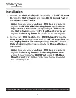
Installation

1. 

Connect an 

HDMI Cable

 (sold separately) to the 

HDMI Input 

Port

 on the 

Matrix Switch

 and to an 

HDMI Output Port

 on 

the 

Video Source Device

.

Note: 

If you are using a 

Locking HDMI Cable

, insert and 

tighten the 

HDMI Cable’s Locking Screw

 into the 

Lock-

ing Screw Hole

 above the corresponding 

HDMI Port

 on 

the 

Matrix Switch

. Using the 

Phillips Head Screwdriver

tighten the 

Locking Screw

. Be careful not to over-tighten.

2. 

Connect an 

HDMI Cable

 to the 

HDMI Output Port

 on the 

Matrix Switch

 and the other end to an 

HDMI Input Port

 on 

the 

Display Device

. The corresponding 

Input LED 

(front of 

Matrix Switch

)

 will light up solid when a 

Display Device

 is 

connected.

Note: 

If you are using a 

Locking HDMI Cable

, insert and 

tighten the 

Locking Screw

 in the 

Locking Screw Hole


above the corresponding 

HDMI Port

. Using the 

Phillips 

Head Screwdriver

, tighten the Locking Screw. Be careful 

not to over-tighten.

Summary of Contents for VS424HD4K60

Page 1: ...anual Revision 11 22 2018 User Manual For the latest information and specifications visit www startech com VS424HD4K60 4x4 HDMI Matrix Switch 4K 60Hz Actual product may vary from photos SKU VS424HD4K6...

Page 2: ...cate the receiving antenna Increase the separation between the equipment and receiver Connect the equipment into an outlet on a circuit different from that to which the receiver is connected Consult t...

Page 3: ...tension L installation et ou le montage du produit doit tre r alis par un professionnel certifi et dans le respect des normes locales et du code de construction local Les c bles y compris les c bles d...

Page 4: ...f r inte g ras n r produkten och eller elledningarna r str mf rda Installation och eller montering f r endast g ras av beh riga yrkespersoner och enligt g llande lokala f rordningar f r s kerhet och...

Page 5: ...Product Information 8 Package Contents 8 Requirements 8 Installation 9 Optional Installation 10 Using RS232 to Control the Matrix Switch 10 Serial Control Settings 11 Using a Network to Control the M...

Page 6: ...tch to a Computer 16 Accessing the Web Interface 16 Switch 18 Setting an I O Position 18 Changing Output Input Name 18 Muting Un muting a Channel 19 Creating an I O Position Preset 19 Loading an I O P...

Page 7: ...ech com support Setting Web Login Timeout 30 Changing Network Settings 31 Resetting the Matrix Switch to Default Settings 32 Upgrading Firmware 32 Telnet Control 34 Accessing the Command Line in Windo...

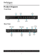
Page 8: ...startech com support Product Diagram Front View Rear View IR Sensor Lock Button LED Indicators Power Button Input Buttons HDMI Locking Screw Holes HDMI Output Ports 4 IR IN RS232 Serial Port Control...

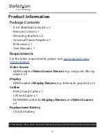
Page 9: ...ower Adapter x 1 IR Receiver x 1 User Manual x 1 Requirements For the latest requirements please visit www startech com VS424HD4K60 Video Source HDMI enabled Video Source Devices e g computer Blu ray...

Page 10: ...ng HDMI Port on the Matrix Switch Using the Phillips Head Screwdriver tighten the Locking Screw Be careful not to over tighten 2 Connect an HDMI Cable to the HDMI Output Port on the Matrix Switch and...

Page 11: ...facing upward If aligned properly the Universal Power Adapter will lock into the Power DC 24V Port 4 Connect the other end of the Universal Power Adapter to an AC Electrical Outlet Optional Installat...

Page 12: ...ol your Matrix Switch over a network Connect an Ethernet Cable sold separately to the Control Port on the Matrix Switch and to an available LAN Port on a Network Device Note See the Web Interface sect...

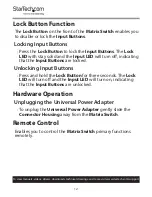
Page 13: ...h stay solid and the Input LED will turn off indicating that the Input Buttons are locked Unlocking Input Buttons Press and hold the Lock Button for three seconds The Lock LED will turn off and the In...

Page 14: ...ding input device 1 4 on Output A Output B 1 4 When selected displays the corresponding input device 1 4 on Output B Output C 1 4 When selected displays the corresponding input device 1 4 on Output C...

Page 15: ...Tech com is not responsible for any damages related to the installation of this product Mounting Requirements Server Rack x 1 Mounting Bracket x 2 Writing Utensil x 1 Phillips Head Screwdriver x 1 M5...

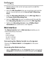
Page 16: ...n M5 Screw two per mounting post through the front Mounting Bracket rail and into the M5 Cage Nut 9 Tighten the Mounting Screws using a Phillips Head Screwdriver be careful not to over tighten Web Int...

Page 17: ...tartech com support Switch 2 Enter the Matrix Switch s default IP address 192 168 1 50 into the web address bar on the Web Browser 3 On the Login screen enter the Username admin and Password admin Log...

Page 18: ...tion 1 On the Switch tab click on an Output The Output will highlight indicating that it was selected Output 2 Click on the Inputs that you want to connect to the selected Output 3 Repeat Steps 1 2 to...

Page 19: ...e button to save the new name Muting Unmuting a Channel 1 On the Switch tab select the Mute Blank Button on the Output Channel you want to mute blank out Note When the Mute Blank Button is selected th...

Page 20: ...ownloads technical drawings and more visit www startech com support Creating an I O Position Preset 1 On the Switch tab set up Input Output positions see Setting an I O Position 2 Click on the Store C...

Page 21: ...screen will appear Preset Set screen 4 Select a Preset Location e g PRESET1 to save the current preset to 5 When you have selected a Preset Location the preset will be saved and you will return to the...

Page 22: ...tartech com support 2 The Preset Recall screen will appear Preset Recall screen 3 Select the I O position preset you want to load 4 The Switch tab will appear with the I O preset loaded Changing a Pre...

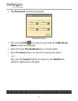
Page 23: ...reset Set screen will appear Preset Set screen 3 Click on the Edit icon next to a preset the Edit Preset Name screen will appear 4 Enter the new Preset Name max 8 characters 5 Click the Save button to...

Page 24: ...D Settings screen 2 From the Set EDID Mode to drop down list select an EDID setting for each of the Inputs that are connected to the Matrix Switch FHD2CH Full High Definition 2 Channel FHDMCH Full Hig...

Page 25: ...ve an EDID setting to the Host Computer 1 On the Switch tab click on the EDID Settings tab the EDID Settings tab will appear EDID Settings screen 2 On the EDID Upload Download section click the Downlo...

Page 26: ...ngs tab will appear EDID Settings screen 2 On the EDID Upload Download section click the Sink EDID Download drop down list and select a sink device 3 Click the Download button the EDID Setting will be...

Page 27: ...load Download section click the Browse button 3 The File screen will appear giving you access to the Host Computers files Select the EDID file you would like to download to the Matrix Switch Note The...

Page 28: ...date the EDID settings or Click the Cancel button to return to the EDID Settings tab without updating System Settings Powering the Matrix Switch On Off 1 From the Switch tab click on the System Settin...

Page 29: ...ab the System Settings tab will appear System Settings screen 2 On the Web User Setting section enter a Username The Username field has an 8 character limitation 3 Enter the current password in the Ol...

Page 30: ...eout Enables you to set the idle time before a user is automatically logged out of the Web Interface 1 On the Switch tab click on the System Setting tab the System Settings tab will appear System Sett...

Page 31: ...Settings Enables you to change set the Matrix Switch s IP mode IP address netmask gateway and MAC address 1 On the Switch tab click on the System Setting tab the System Settings tab will appear Syste...

Page 32: ...ab click on the System Settings tab the System Settings tab will appear System Settings screen 2 On the Reset to Defaults section click on the Routing Reset button to reset all routing settings or Cli...

Page 33: ...t a USB A Device 1 Connect a Mini USB Cable to the Service Port on the Matrix Switch and connect the other end to a USB Port on the Host Computer 2 From the Switch tab click on the System Settings tab...

Page 34: ...mmand Line in Windows 1 From the Start menu type cmd in the Search field 2 Press Enter Accessing the Command Line in macOS From the Go menu select Application Utilities Terminal Command Line Interface...

Page 35: ...nd Commands are not case sensitive Commands also work with RS232 serial Command Description A N Switch Output A to Input N N 1 4 B N Switch Output B to Input N N 1 4 C N Switch Output C to Input N N 1...

Page 36: ...N Creates a preset input output setting using N N 1 4 NAME N N1 Names port N as N1 N 1 4 N1 LENGTH 8 MAX ST Displays the Switch s current firmware version EM N N1 Sets port N s EDID mode to N1 EM N Di...

Page 37: ...ages whether direct or indirect special punitive incidental consequential or otherwise loss of profits loss of business or any pecuniary loss arising out of or related to the use of the product that e...

Page 38: ...tools StarTech com is an ISO 9001 Registered manufacturer of connectivity and technology parts StarTech com was founded in 1985 and has operations in the United States Canada the United Kingdom and Ta...

Reviews: