background image

12

To view manuals, videos, drivers, downloads, technical drawings, and more visit www.startech.com/support

Installation

Leveling the Rack

The Rack will need to be properly level prior to the installation 

of any Rack Equipment, to ensure stability. The surface the Rack 

is located must also be flat and level to support the weight of 

the Rack and mounted equipment.

1. 

Determine the location of the Rack, then use the Level to 

ensure that the surface is a flat level surface. 

Summary of Contents for RK2537BKM

Page 1: ...Manual Revision 09 18 2018 User Manual For the latest information and specifications visit www startech com RK2537BKM 25U Rack Enclosure Actual product may vary from photos SKU RK2537BKM...

Page 2: ...se harmful interference to radio communications However there is no guarantee that interference will not occur in a particular installation If this equipment does cause harmful interference to radio o...

Page 3: ...Where they occur these references are for illustrative purposes only and do not represent an endorsement of a product or service by StarTech com or an endorsement of the product s to which this manua...

Page 4: ...tension L installation et ou le montage du produit doit tre r alis par un professionnel certifi et dans le respect des normes locales et du code de construction local Les c bles y compris les c bles d...

Page 5: ...ce Tipping hazard Extending multiple components from this enclosure increases the chance that the enclosure will tip over To avoid this risk do not extend more than one component from the enclosure Do...

Page 6: ...sque de basculement Pour viter ce risque n tendez pas plus d un composant partir du rack de serveur Ne placez aucun objet sur ce rack de serveur et n empilez pas le rack sur un autre rack N approchez...

Page 7: ...a Pericolo di ribaltamento L estensione di pi componenti dal box esterno aumenta il rischio di ribaltamento del box esterno Per evitare questo rischio non estendere pi di un componente dal box esterno...

Page 8: ...s aumenta las posibilidades de peligro de vuelco de la caja Para evitar dicho riesgo no a ada m s que un solo componente No coloque ning n elemento encima de la caja y no apile la caja encima de otra...

Page 9: ...g Houd vloeistof uit de buurt van deze behuizing Zorg dat u de behuizing installeert op een plaats die geschikt is voor het gecombineerde gewicht van de behuizing en de apparatuur die u in de behuizin...

Page 10: ...ts 4 Product Information 10 Package Contents 10 Requirements 10 Unpacking the Rack 11 Installation 12 Leveling the Rack 12 Installing the Cage Nuts 13 Removing the Front and or Rear Door 15 Removing t...

Page 11: ...1 M6 Cage Nuts x 104 M6 Screws x 104 A Pair of Keys x 1 Wrench x 1 10 ft 3 m Hook and Loop Tape x 1 User Manual x 1 Requirements For the latest requirements please visit www startech com RK2537BKM Ins...

Page 12: ...ve the Tie Straps from the shipping carton 3 Remove the shipping carton from the shipping pallet being careful not to tip the Rack 4 The 1U Cabinet Shelf box will be shipped in the Rack s interior 5 R...

Page 13: ...k The Rack will need to be properly level prior to the installation of any Rack Equipment to ensure stability The surface the Rack is located must also be flat and level to support the weight of the R...

Page 14: ...Levelers by turning it clockwise until the base of the Leveler is tightly pressed against the surface supporting the weight of the Rack Number Description 1 Leveler 3 Place the Level on the top of th...

Page 15: ...or interior of the Rack 2 Using a 13 mm Socket and Wrench insert two of the Bolts through the Bracket and into the Rack 3 Insert the other two Bolts through the Bracket and into the surface you are s...

Page 16: ...of the Cage Nut Insert the Cage Nut Clamps into the Cage Nut Hole and release the Cage Nut or Use the included Cage Nut Wrench to install the Cage Nuts into the Rack 3 Use the M6 Screws to secure the...

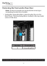
Page 17: ...rt Removing the Front and or Rear Door Note At least two people are required when removing or reinstalling the door from the Rack 1 Unplug the Grounding Wire connecting the Door to the Door Frame The...

Page 18: ...cal drawings and more visit www startech com support 2 With the door open at a 90 degree angle to the Rack frame lift the door from out of its hinges and pull outward to remove it from the door frame...

Page 19: ...moving the Side Panels Note At least two people are required when removing or reinstalling the Side Panel from the Rack 1 While supporting the top portion of the Side Panel pull the Locking Latch on t...

Page 20: ...al drawings and more visit www startech com support 2 Slowly tilt the top portion of the Side Panel away from the Rack Frame 3 While supporting the weight of the Side Panel pull the bottom of the Side...

Page 21: ...to the lip on the Rack Frame 3 Push the top of the Side Panel into the Rack Frame until you hear it click lock into place Removing the Roof Panel The Roof Panel can be removed in order to run cabling...

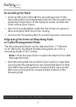
Page 22: ...Door from closing 3 Connect the Grounding Wire to an earth ground connection Adjusting the Vertical Mounting Rails or Cable Management Rails The Mounting Rail Depth can be adjusted from 7 180mm to 35...

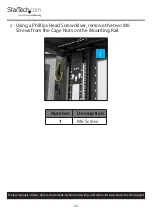
Page 23: ...videos drivers downloads technical drawings and more visit www startech com support 2 Using a Phillips Head Screwdriver remove the two M6 Screws from the Cage Nuts on the Mounting Rail Number Descrip...

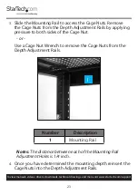
Page 24: ...the Depth Adjustment Rails by applying pressure to both sides of the Cage Nut or Use a Cage Nut Wrench to remove the Cage Nuts from the Depth Adjustment Rails Number Description 1 Mounting Rail Notes...

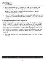
Page 25: ...the Cage Nuts Use a Phillips Head Screwdriver to tighten the M6 Screws Baying Multiple Racks Together Use the Baying Brackets to connect or Bay the Rack to multiple racks There are four Baying Bracket...

Page 26: ...ech com support 2 Open the Rack s Front Door allowing you access to the inner door frame where the Baying Brackets are located Number Description 1 Baying Bracket 3 Move the racks close enough so that...

Page 27: ...crew Hole 4 Using a Phillips Head Screwdriver Loosen the Baying Bracket Screw holding the Baying Bracket in place 5 Turn the Baying bracket enough to align the Baying Bracket with the Baying Hole 6 In...

Page 28: ...discretion The warranty covers parts and labor costs only StarTech com does not warrant its products from defects or damages arising from misuse abuse alteration or normal wear and tear Limitation of...

Page 29: ...tools StarTech com is an ISO 9001 Registered manufacturer of connectivity and technology parts StarTech com was founded in 1985 and has operations in the United States Canada the United Kingdom and Ta...

Reviews: